 |
|||
|
|
|||
|
Page Title:
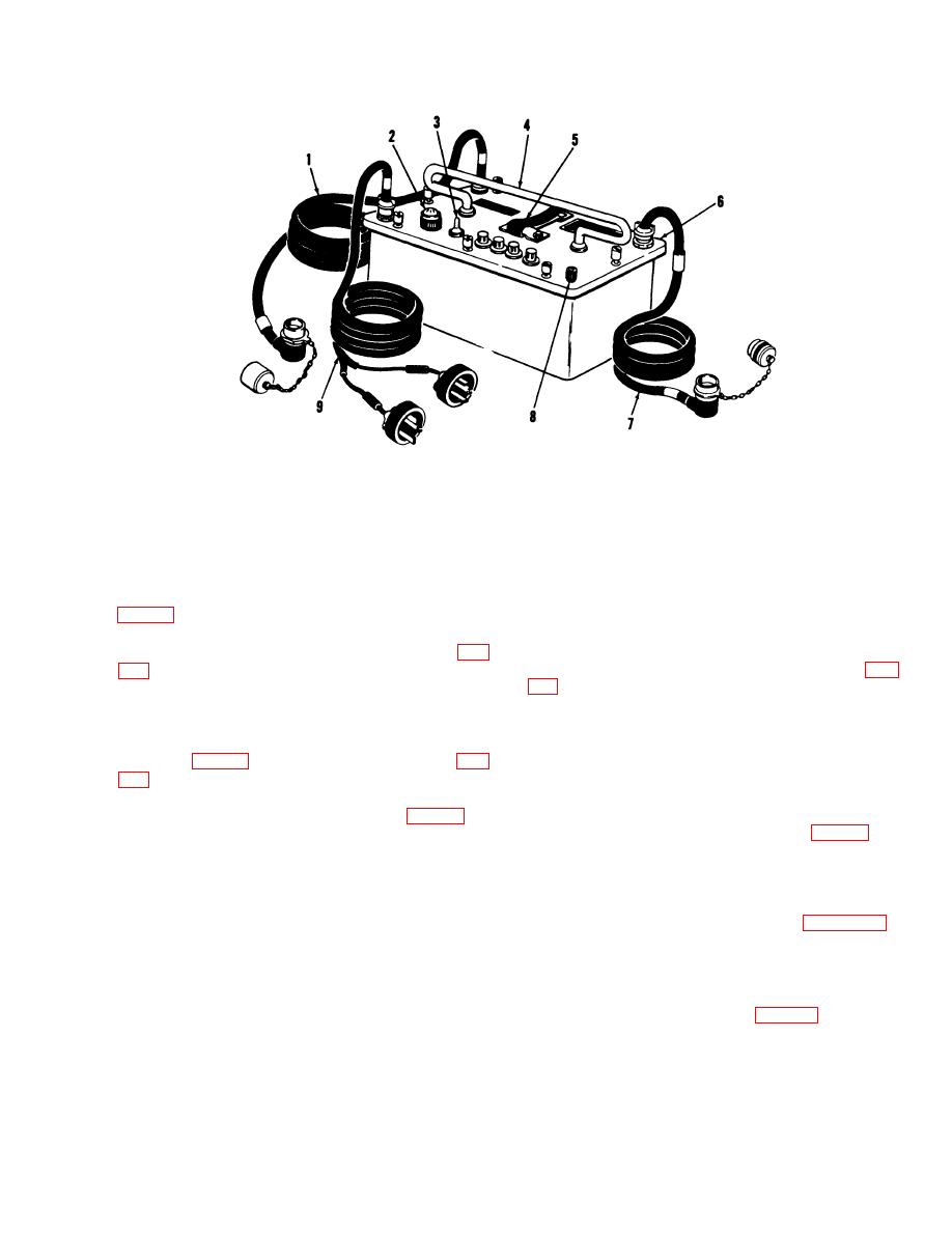
Figure 2-2. M10 power supply. |
|
||
| ||||||||||
|
|
 TM 3-6665-225-12
Figure 2-2. M10 power supply.
fingertight.
a. M43 Detector Unit.
(6) Verify that catches (6) of pump assem-
(1) Check that RAINSHIELD assembly (1,
bly (7) are secured.
(7) Check that turnlock fastener (11) of
and are installed in handle (2).
electronic module (10) is locked in position.
(2) Release four clamping catches (12, fig.
(8) Install detector unit assembly (6, fig.
bottom case assembly (9). Place detector unit
clamping catches (12).
assembly (6) on its side with AIR FILTER plug
b. M42 Alarm Unit
(7) up.
(3) Check that bottom case assembly con-
NOTE
Notify personnel within audible range
that test of the M42 alarm unit is to be
broken, or bent.
made.
(4) Check that detector cell (8, fig. 1-3) is
(1) Position selector switch (8, fig. 1-5) to
securely installed.
TEST. If M42 alarm unit is operative, loud-
(5) For new equipment, install detector cell
speaker (5) will sound, and ALARM-RED indica-
as follows:
tor (3) will flash.
(a) Remove strap from bail (9).
(2) If M42 alarm unit does not operate in
(b) Remove detector cell can from handle.
TEST mode, install fresh batteries (para 3-16).
(c) Remove detector cell from can.
Repeat (1) above.
(d) Remove plastic bag, two caps, and
(3) Position selector switch (8) to HORN
plug.
OFF.
(e) Dampen outside of two detector cell
c. M10 Power Supply
ports with a few drops of water.
(1) Unbuckle strap (5, fig. 2-2), unwind
(f) Position detector cell (8) so that its
STANDBY BATTERY cable (W3) (1), DETEC-
ports are alined with their corresponding fittings
TOR POWER cable (W2) (7), and 115V/220V
in chassis (4). Press detector cell into place in
cable (W1) (9) from handle (4).
chassis.
(2) Connect 115V/220V cable (W1) (9) to
(g) Center bail (9) on the bottom of
power source.
detector cell (8) and turn lobed nut clockwise until
2-3
|
|
Privacy Statement - Press Release - Copyright Information. - Contact Us |
