 |
|||
|
|
|||
|
|
|||
| ||||||||||
|
|
 TM 3-6665-22512
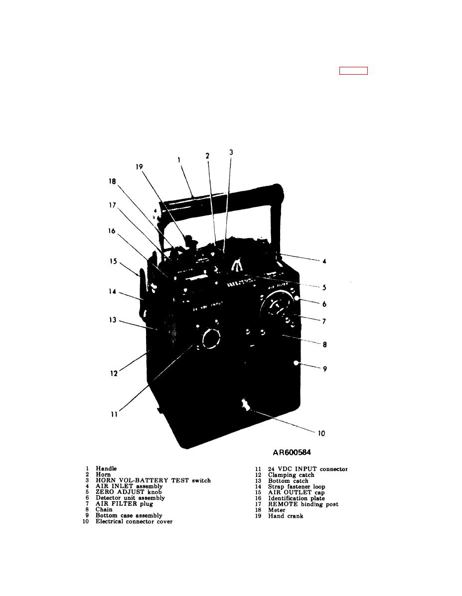
two strap fastener loops (14), an AIR OUTLET
bottom case assembly (9) by four clamping
cap (15), an identification plate (16), two RE-
catches (12).
MOTE binding posts (17), a meter (18), and hand
a. Detector Unit Assembly. Attached to the
crank (19). The handle (2, fig. 1-3) contains a
detector unit assembly (6) are a handle (1), a horn
R A I N S H I E L D assembly (1) and a FLOW-
(2), a BATTERY TEST switch and HORN VOL
METER (3). A chassis (4) is mounted to the
control (3), an AIR INLET assembly (4), a ZERO
underside of the detector unit assembly. Mounted
ADJUST knob (5), and AIR FILTER plug (7), an
to the chassis (4) are four electrical contacts (5); a
electrical connector cover (10), two chains (8) that
pump assembly (7), secured by two catches (6); a
attach the AIR FILTER plug and connector
detector cell (8), secured by a bail (9); an
cover, a 24 VDC INPUT receptacle (11), four
electronic module (10), secured by a turnlock
clamping catches (12), four bottom catches (13),
Figure 1-2. M43 detector unit.
1-4
|
|
Privacy Statement - Press Release - Copyright Information. - Contact Us |
