 |
|||
|
|
|||
|
Page Title:
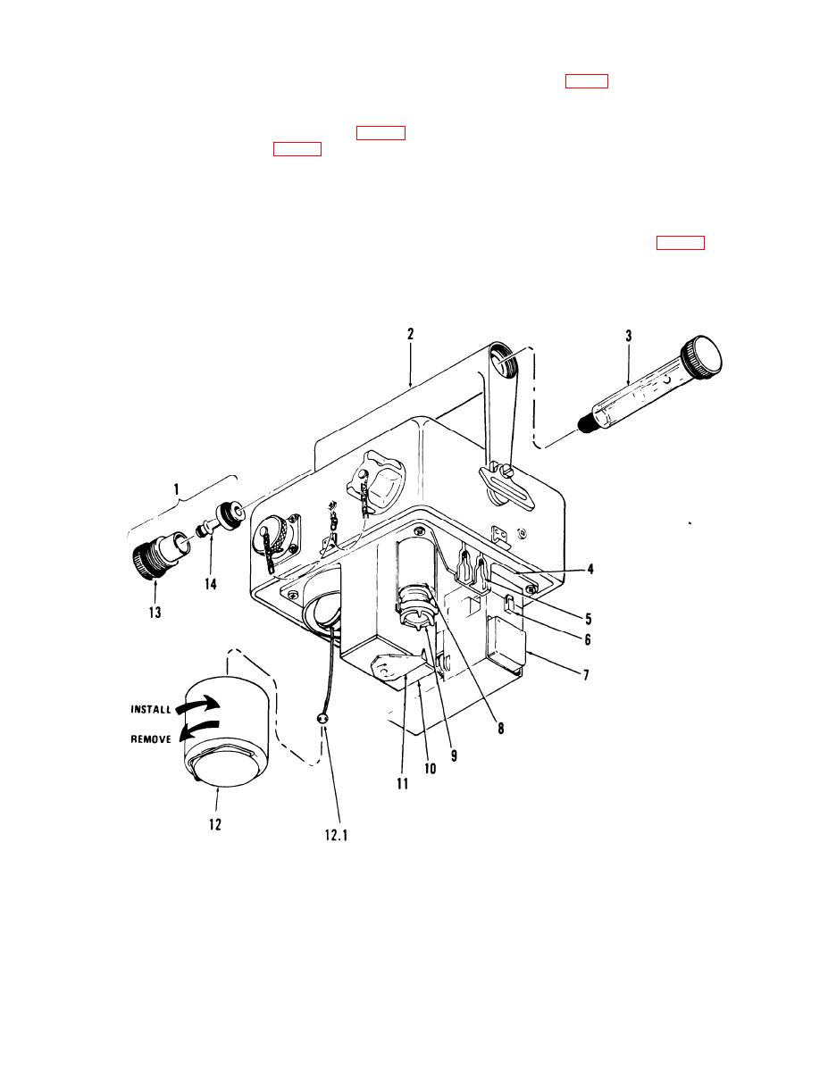
Figure 1-3. Detector unit assembly. |
|
||
| ||||||||||
|
|
 TM 3-6665-225-12
mate with contacts (5, fig. 1-8) in the detector as-
fastener (11); and a reservoir assembly (12), which
sembly. When the M43 detector unit is operated
screws into the chassis (4).
below 40F., the heaters are automatically turned
b. Bottom Case Assembly. Mounted to the
on and off to maintain 40F. within the bottom
outside of the bottom case assembly (9, fig. 1-2)
case assembly.
are an instruction plate (3, fig. 1-4); two catches
1-10. M42 Alarm Unit
(4) that attach a BA3517/U battery; and four
The M42 alarm unit, when connected to the M43
clamping catches (5) that secure the bottom case
detector unit provides a remote audible and visual
assembly to the detector unit assembly. A seal (1)
signal or visual signal only whenever the M43
fits in a groove around the top of the bottom case
detector unit senses chemical agent. The M42
assembly to insure that the interior of the M43
alarm unit consists of a panel (1, fig. 1-5) secured
detector unit is watertight and airtight when the
to a housing (4) by four knurled screws (9). The
bottom case assembly is secured to the detector
panel contains an ALARM-RED indicator (3), a
unit assembly. Electrical resistance heaters are
loudspeaker (5), an identification plate (6), two
embedded in the double-walled case of the bottom
binding posts (7), and a selector switch (8). Two
case assembly. Two pairs of heater contacts (2)
1
RAINSHIELD assembly
9 Bail
2
Handle
10 Electronic module
3
FLOWMETER
11 Turnlock fastener
4
Chassis
12 Reservoir assembly
5
Contact
12.1 Weight assembly
6
Catch
13 Rainshield
7
Pump assembly
14 Adapter
8
Detector cell
Figure 1-3. Detector unit assembly.
1-5
|
|
Privacy Statement - Press Release - Copyright Information. - Contact Us |