 |
|||
|
|
|||
|
Page Title:
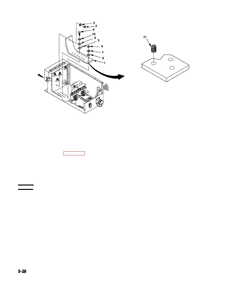
Figure 5-14. Bus Bar Maintenance |
|
||
| ||||||||||
|
|
 TM 9-6115-661-13&P
NOTE
The bus bar is physically connected to LO of the switch box assembly and
is a common ground. Leads connected to bus bar may be connected to
any terminal on the bus bar.
5. Remove cap screws (4, figure 5-14), lock washers (10), flat washers (9) and electrical leads (5) from
bus bar (1).
6. Remove nut (3) and lock washer (2).
7. Remove nut (6), lock washer (7), and flat washer (8) and bus bar (1).
REPAIR
Disconnect and label electrical leads (5) connected to bus bar.
1.
2.
Remove defective insert (11).
Using insertion tool, rotate handle CCW until you can install insert (11) into barrel with tang
3.
toward hole.
4.
Turn handle CW until one thread of insert protrudes from hole.
5.
Position over bus bar and turn handle CW until insert is installed.
6.
Turn handle CCW to remove insertion tool.
Install small punch into hole until it contacts tang. Break off and remove tang.
7.
|
|
Privacy Statement - Press Release - Copyright Information. - Contact Us |
