 |
|||
|
|
|||
|
Page Title:
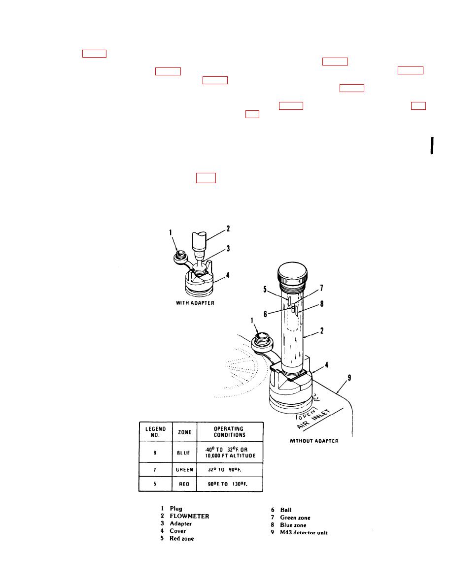
Figure 2-6. FLOWMETER application. |
|
||
| ||||||||||
|
|
 TM 3-6665-225-12
k. Disconnect power source from the 24 VDC
cover (4, fig. 2-6). Press down on top of FLOW-
INPUT connector (11, fig. 1-2) of M43 detector unit.
METER. Ball (6) must rise and float within correct
Position M42 alarm unit selector switch (8, fig. 1-5)
zone for ambient temperature (fig. 2-6).
to HORN ON or connect wire to M43 detector unit
REMOTE binding post (17, fig. 1-5).
in. Press in hand crank (2), rotate crank clockwise
l. Remove protective cap from sensitivity check
50 turns, and release it.
bottle (6, fig. 1-6). Unscrew AIR FILTER plug (4, fig.
NOTE
Keep hand crank in down position, not
m. Invert sensitivity check bottle, and, while
pressed in.
holding dropper tip 1/2-inch over center of black
j. Press and rotate ZERO ADJUST knob (5) until
side of filter material (2), allow two drops of solu-
meter (1) indicates in ZERO ADJUST zone (blue).
tion to fall on filter.
Release knob. After 5 minutes, press and reset, if
n. Immediately replace air filter (3) in M43
necessary.
NOTE
If new detector cell was installed (para
2-6a(5)), M43 detector unit must be allowed
to operate for 1 hour to stabilize detector
cell before proceeding.
2-7
Change 2
Figure 2-6. FLOWMETER application.
|
|
Privacy Statement - Press Release - Copyright Information. - Contact Us |