 |
|||
|
|
|||
|
Page Title:
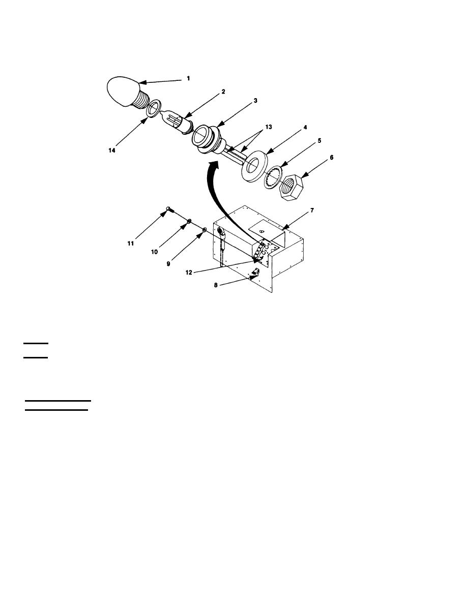
Figure 4-13. Indicator Light Replacement. |
|
||
| ||||||||||
|
|
 TM 9-6115-663-13&P
TEST
Using multimeter, measure continuity between pins (13). If no continuity replace lamp (2). If continuity
exists, replace indicator housing (3).
INSTALLATION
1. Remove mounting nut (6), internal tooth lock washer (5), and O-ring (4) from new indicator
housing (3).
2. Install O-ring (4) on indicator housing (3) and insert indicator housing (3) through control panel
assembly (12).
3. Install internal tooth lock washer (5) on indicator housing (3).
4. Install mounting nut (6) on indicator housing (3).
5. Solder wires to the applicable terminals (13) and remove tags.
6. Position control panel assembly (12) with gasket on switch box cover (15) and align mounting holes.
|
|
Privacy Statement - Press Release - Copyright Information. - Contact Us |
