 |
|||
|
|
|||
|
Page Title:
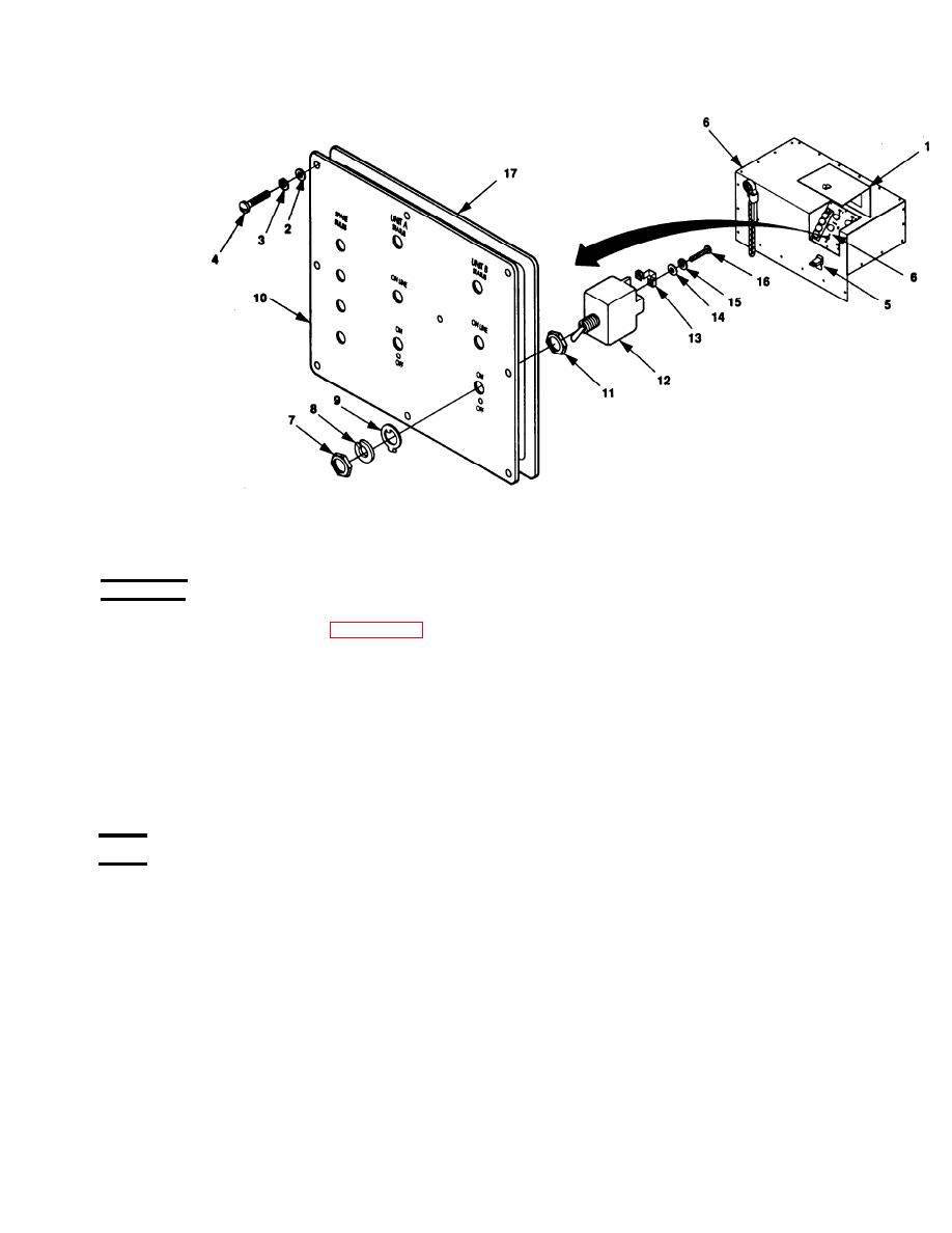
Figure 4-12. Switch Replacement |
|
||
| ||||||||||
|
|
 TM 9-6115-663-13&P
REMOVAL
1. Release clamping catch (5, Figure 4-12) and open the control panel access cover (1).
2. Remove 8 screws (4), flat washers (2), and lock washers (3). Remove control panel assembly (10).
3. Tag wires on terminals 3, 4, and 6 of switch (12).
4. Remove terminal screws (16), lock washers (15), flat washers (14), and conductor bus (13) from
switch terminals.
5. Remove nut (7), lock washer (8), locking ring (9), and switch (12).
TEST
1. Set multimeter for continuity test.
2. With switch (12) in center position, check continuity of switch between terminals 3 and 5.
3. If no continuity in step 2, replace switch.
|
|
Privacy Statement - Press Release - Copyright Information. - Contact Us |
