 |
|||
|
|
|||
|
Page Title:
Figure 5-15. Contactor Maintenance. |
|
||
| ||||||||||
|
|
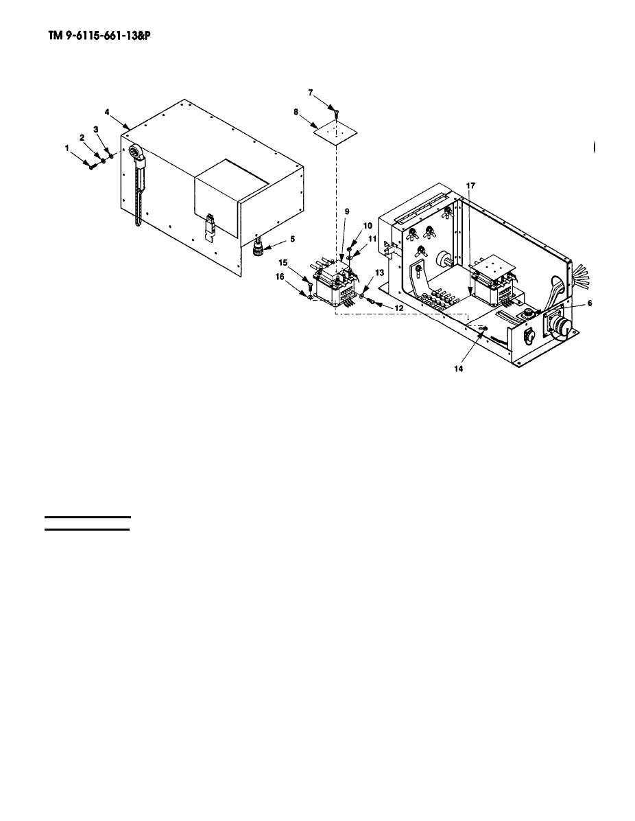 6. Remove six nuts (10) and washers (11). Tag and remove six leads from contactor (9).
7. Remove eight terminal screws (12) and washers (13). Tag and remove wiring harnesses from
contactor (9).
8. Remove four nuts (14), screws (15), flat washers (16), and contactor (9).
INSTALLATION
1.
Position new contactor (9) over mounting holes in bracket (17).
2.
Install a flat washer (16) on each screw (15).
3.
Install four screws (15), flat washers (16), and nuts (14) to secure contactor (9).
4.
Remove four screws (7) and terminal shield (8) from the new contactor (9).
Connect the wiring harness and six electrical leads and install washers (13 and 11), screws (12), and
5.
nuts (10).
Install terminal shield (8) on new contactor (9) and secure with screws (7).
6.
7.
Connect P3 (5) to J4 (6) and position switch box cover (4) over the switch box assembly.
Install flat washers (3), lock washers (2) and screws (1) that secure switch box cover (4).
8.
5-30
|
|
Privacy Statement - Press Release - Copyright Information. - Contact Us |
