 |
|||
|
|
|||
|
Page Title:
Table 3. Directional Signal Systems Troubleshooting Procedures - continued |
|
||
| ||||||||||
|
|
 TM 9-2320-361-24-1
0013 00
LIGHTING AND WIPER SYSTEM TROUBLESHOOTING (Contd)
Table 3. Directional Signal Systems Troubleshooting Procedures (Contd).
MALFUNCTION
TEST OR INSPECTION
CORRECTIVE ACTION
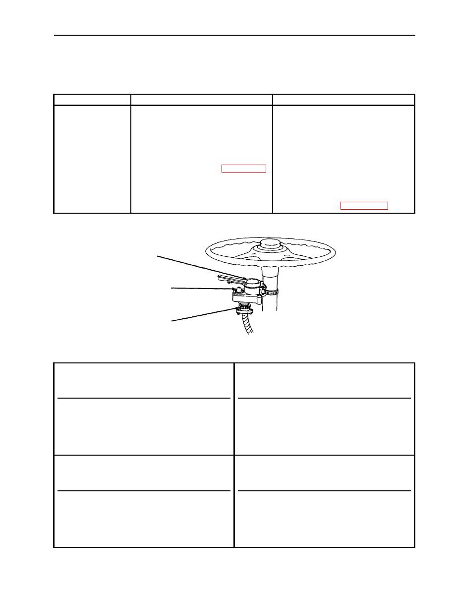
Test turn signal control unit continuity.
4. TURN SIGNALS
OPERATE
1. Place battery switch in OFF
INCORRECTLY
position.
WITH TURN
2. Remove cable connector from
SIGNAL CONTROL
turn signal switch.
LEVER
3. Remove indicator lamp from
IN ONE OR MORE
turn signal switch (WP 0102 00).
POSITIONS
4. Set multimeter to RX 1 scale.
5. Check circuits according to
If any circuit does not test as shown in
Control Unit Test Chart, below. the Control Unit Test Chart, replace
turn signal switch (WP 0102 00).
TURN
SIGNAL
SWITCH
TURN
SIGNAL
LAMP
CABLE
CONNECTOR
CONTROL UNIT TEST CHART
A. Directional signal control lever in NEUTRAL
C. Directional signal control lever in RIGHT TURN
position
position
FROM PIN
TO PIN
INDICATION
FROM PIN
TO PIN
INDICATION
H
A
OPEN
F
G
SHORTED
H
B
OPEN
H
A
SHORTED
H
C
OPEN
H
E
SHORTED
H
E
OPEN
H
B
OPEN
D
C
SHORTED
H
C
OPEN
D
E
SHORTED
D
C
SHORTED
F
G
OPEN
D
E
OPEN
B. Directional signal control lever in LEFT TURN
D. Directional signal control lever in HAZARD
position
WARNING position
FROM PIN
TO PIN
INDICATION
FROM PIN
TO PIN
INDICATION
H
B
SHORTED
H
A
SHORTED
H
C
SHORTED
H
B
SHORTED
H
A
OPEN
H
C
SHORTED
H
E
OPEN
H
E
SHORTED
F
G
SHORTED
D
E
OPEN
D
E
SHORTED
D
C
OPEN
D
C
OPEN
F
G
SHORTED
|
|
Privacy Statement - Press Release - Copyright Information. - Contact Us |
