 |
|||
|
|
|||
|
Page Title:
Table 4. Trailer Connection System Troubleshooting Procedures. |
|
||
| ||||||||||
|
|
 TM 9-2320-361-24-1
0013 00
LIGHTING AND WIPER SYSTEM TROUBLESHOOTING (Contd)
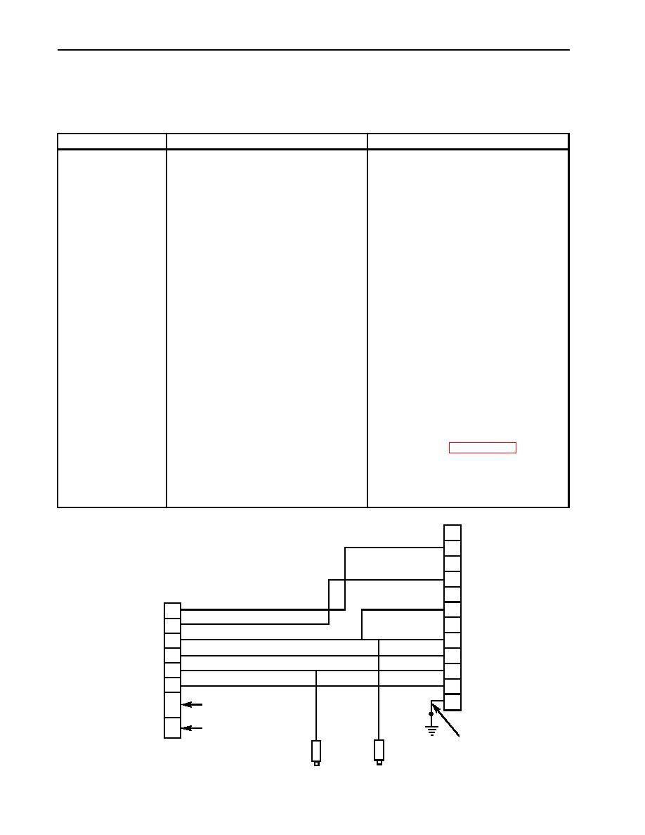
Table 4. Trailer Connection System Troubleshooting Procedures.
MALFUNCTION
TEST OR INSPECTION
CORRECTIVE ACTION
NOTE
ONE OR MORE
TRAILER LIGHTS
For stoplight circuit test, brake pedal
INOPERATIVE
must be depressed and air pressure
maintained.
Test 1. Test trailer receptacle voltage.
1. Place main light switch lever
in position corresponding to
inoperative lamp.
2. Set multimeter to voltage
range that will measure
24 VDC.
1. If battery voltage is present,
3. Connect negative lead of
disconnect and reconnect male
multimeter to trailer receptacle
connector to ensure positive
pin D. Touch positive lead to
connection. If trailer lamps still do
appropriate trailer receptacle
not light, check trailer lighting
pin of circuit being tested.
system.
Light switch must be in
corresponding position.
2. If battery voltage is not present at
one or more of the pins being tested,
continue with test 2.
Test 2. Test trailer receptacle ground.
If continuity is not present, repair or
1. Set multimeter to RX 1 scale.
replace lead 90 (WP 0090 00).
2. Connect negative lead of
multimeter to frame ground.
Touch positive lead to pin D of
trailer receptacle.
L
K
N
J
M
H
TRAILER
H
RECEPTACLE
C
G
D
A
C
B
REAR
E
E
HARNESS
B
F
D
INTAKE FUEL PUMP
F
A
FUEL TANK SENDING UNIT
90
489
490
CLEARANCE
B.O. CLEARANCE
|
|
Privacy Statement - Press Release - Copyright Information. - Contact Us |
