 |
|||
|
|
|||
|
Page Title:
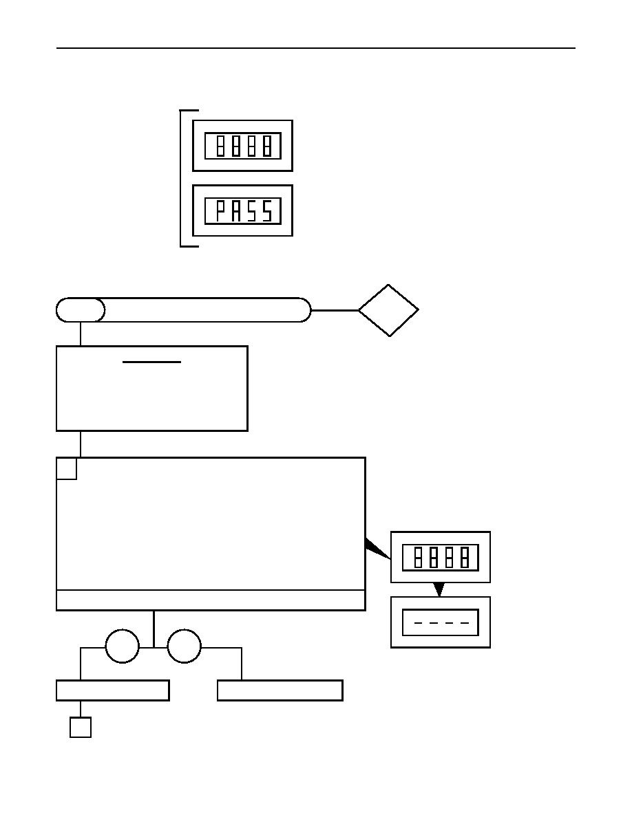
Table 2. STE/ICE-R GO-Chain Tests |
|
||
| ||||||||||
|
|
 TM 9-2320-386-24-1-1
0016 00
Table 2. STE/ICE-R GO-Chain Tests
INDICATES VTM IS PROPERLY
CONNECTED AND READY
FOR TESTS
INDICATES TEST
SUCCESSFULLY COMPLETED
DCA
VTM CONNECTIONS AND CHECKOUT
G01
MODE
CAUTION
Do not connect or disconnect the VTM
while the vehicle is running.
Connect DCA cable W1 to the VTM
before connecting to the diagnostic
connector.
CONNECT VTM TO VEHICLE DIAGNOSTIC CONNECTOR:
1
PULL OFF the VTM power switch.
Connect P1 of the DCA cable W1 to the VTM.
Connect DCA cable W1 to the DCA connector under the
passenger's side of the instrument panel.
Position vehicle battery switch to ON position.
PUSH ON the VTM power switch.
Verify that the display indicated .8.8.8.8 for approximately
2 seconds and then changes to .
Does the VTM display .8.8.8.8 and then change to ?
After 2 seconds.
YES
NO
Proceed to step 3.
Proceed to next page.
3
|
|
Privacy Statement - Press Release - Copyright Information. - Contact Us |