 |
|||
|
|
|||
|
|
|||
| ||||||||||
|
|
 TM 9-2320-209-34-2-3
c.
Replacement.
FRAME 1
1.
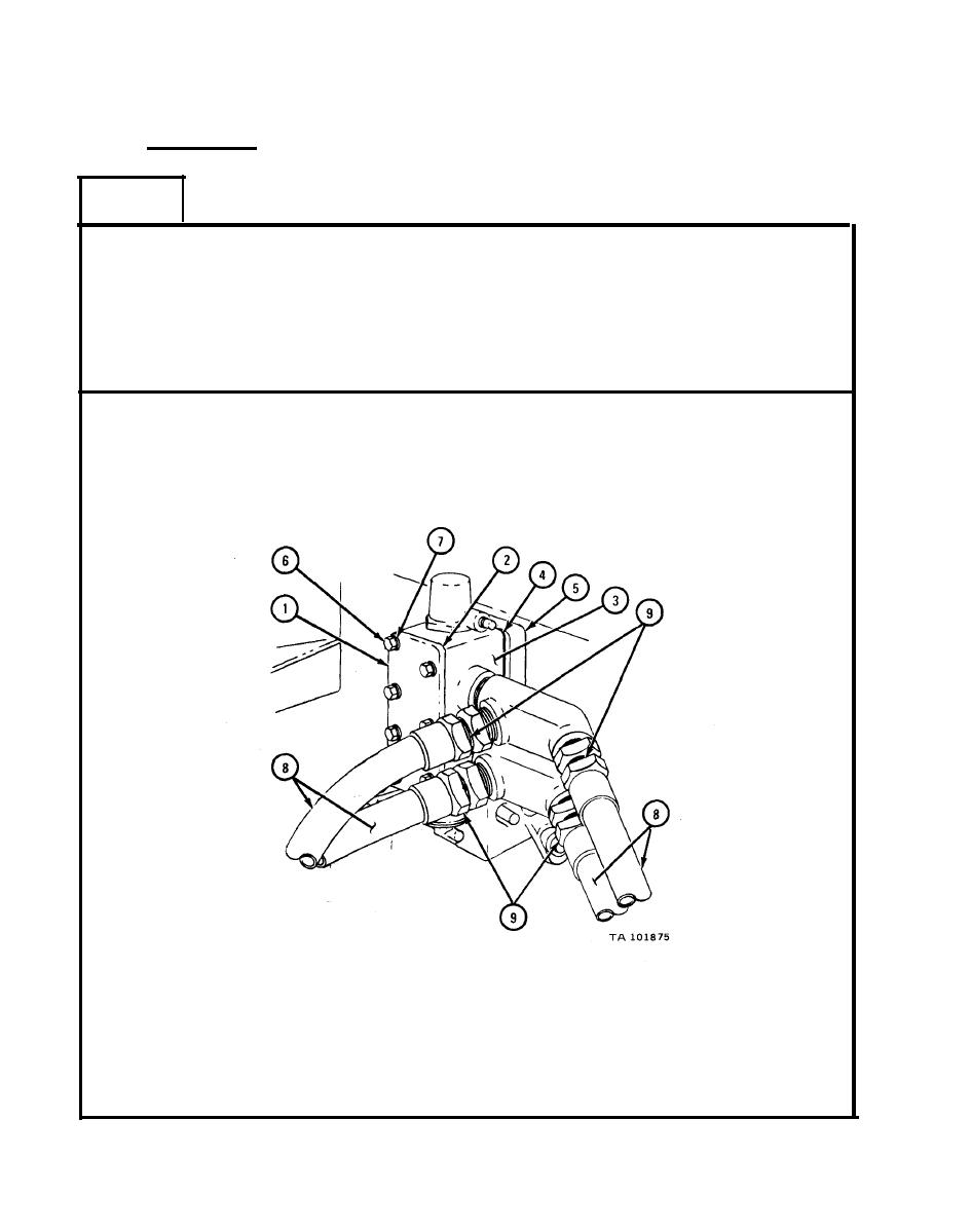
Put control valve cover (1), gasket (2), control valve body (3), and
gasket (4) in place on subframe (5), aligning holes.
2.
Screw in and tighten seven screws (6) and lockwashers (7).
3.
Put four hydraulic lines (8) in place and screw on and tighten four
coupling nuts (9).
GO TO FRAME 2
|
|
Privacy Statement - Press Release - Copyright Information. - Contact Us |