 |
|||
|
|
|||
|
|
|||
| ||||||||||
|
|
 TM 9-2320-209-34-2-2
Removal.
b.
NOTE
Except where noted, removal and replacement pro-
cedures for the left and right fenders are the same.
FRAME
1
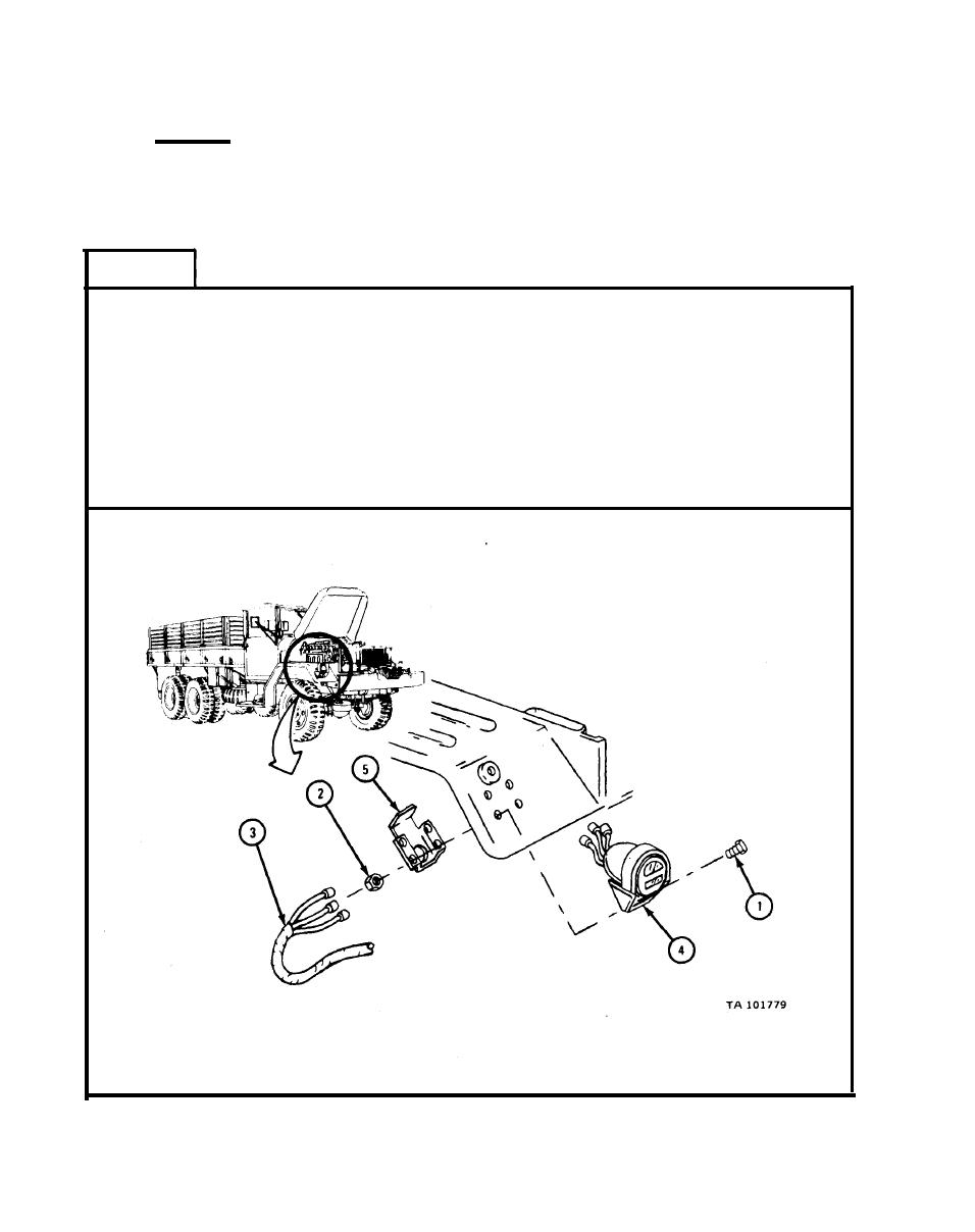
Take out four screws (1) and four self-locking nuts (2).
1.
NOTE
Tag three leads (3) and three leads on light assembly (4)
so they can be put back in the same place.
2.
Take three leads (3) off light assembly (4).
3. Take off light assembly (4) and protector box (5).
IF WORKING ON LEFT FENDER, GO TO FRAME 2.
IF WORKING ON RIGHT FENDER, GO TO FRAME 3
|
|
Privacy Statement - Press Release - Copyright Information. - Contact Us |