 |
|||
|
|
|||
|
|
|||
| ||||||||||
|
|
 TM 9-2320-209-20-3-4
b.
Replacement and Adjustment.
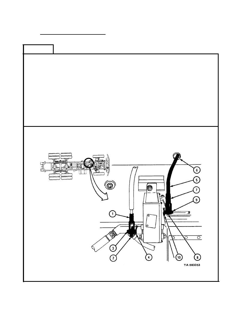
FRAME 1
Put clevis (1) on lever (2) and put clevis pin (3) through holes in clevis and
1.
lever.
2.
Put cotter pin (4) through hole in clevis pin (3) and using pliers, bend open
ends of cotter pin.
Put rod assembly (5) through hole in frame crossmember (6) as shown. Turn
3.
rod assembly so it is in position shown and put clevis (7) on lever (8).
Put clevis pin (9) through holes in clevis (7) and lever (8).
4.
Put cotter pin (10) through hole in clevis pin (9) and using pliers, bend open
5.
ends of cotter pin.
Push lever (2) as far forward as it will go.
6.
GO TO FRAME 2
|
|
Privacy Statement - Press Release - Copyright Information. - Contact Us |