 |
|||
|
|
|||
|
Page Title:
ELECTRICAL TROUBLESHOOTING - continued |
|
||
| ||||||||||
|
|
 TM 9-2320-386-24-1-1
0012 00
Electrical Troubleshooting (Contd)
MALFUNCTION
TEST OR INSPECTION
CORRECTIVE ACTION
Step 1. Check harness connector for continuity and voltage.
a. Separate instrument cluster from instrument panel (WP 0094 00).
b. Disconnect harness connector from tachometer.
NOTE
Place accessory/battery switch in ON position when checking pin A
to pin D, and pin B to pin C. Switch is in OFF position when
checking pin C to pin D, and pin D to ground.
c. Using multimeter, test harness connector as shown in chart below. Replace
tachometer if harness connector passes test (WP 0095 00).
d. If reading from pin B to pin C is not within limits, perform step 2.
Tachometer Harness Connector Test
TEST POINT
READING
Pin
A to pin D
28 Vdc
Pin
B to pin C
0.5-5 Vdc; 0.2 Vdc max.
Pin
C to pin D
0 ohms
Pin
D to ground
0 ohms
Step 2. Check if magnetic sensor is defective.
a. Check that 2-pin connector is intact with front wiring harness.
b. Reset gap of magnetic sensor.
c. Loosen jamnut and turn magnetic sensor clockwise to bottom-out on flywheel.
d. Turn magnetic sensor 1 to 1-1/2 turns counterclockwise and tighten jamnut against
flywheel housing.
e. Retest pin B to pin C. If reading is not within limits, replace magnetic speed sensor
END OF TESTING!
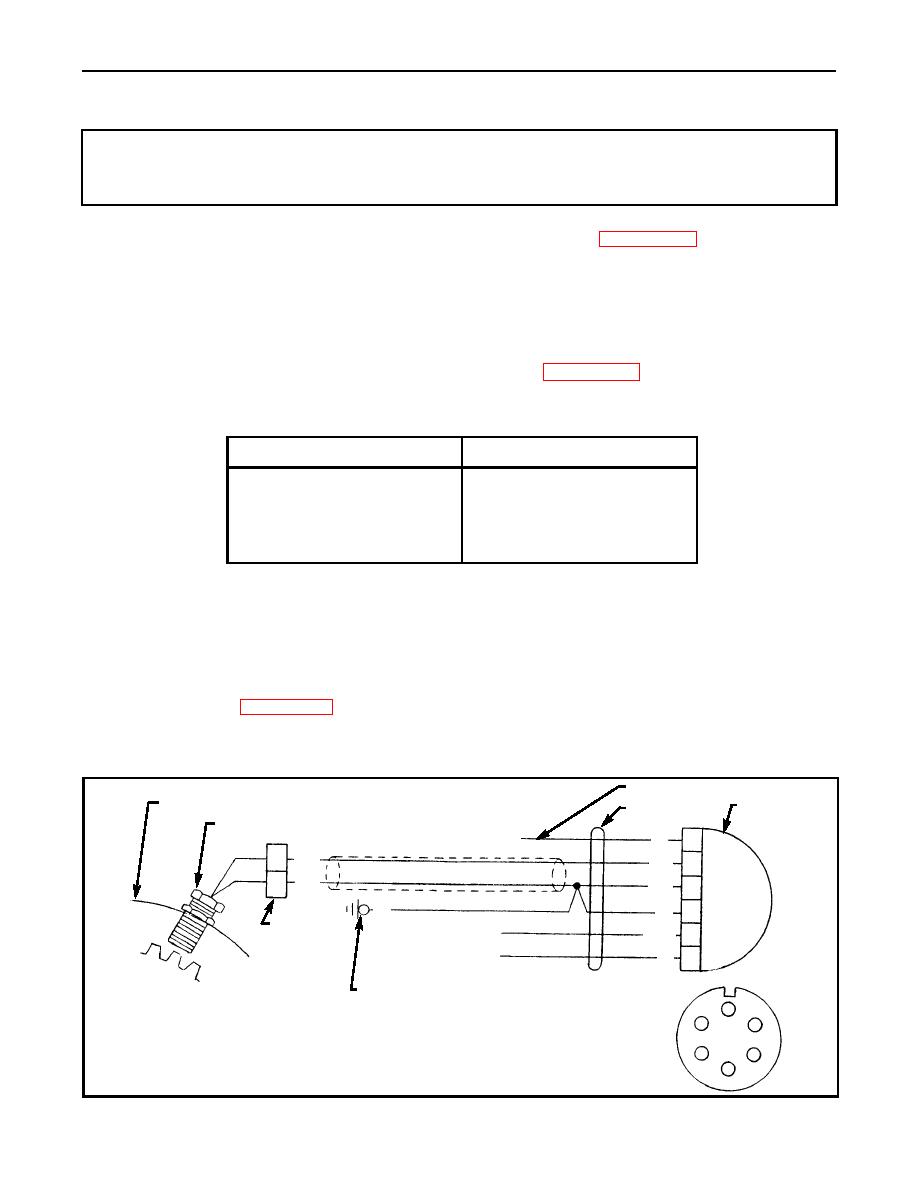
WIRING DIAGRAM OF TACHOMETER CIRCUIT
SHIELDING
FLYWHEEL HOUSING
TACHOMETER
FRONT HARNESS
MAGNETIC SENSOR
(FROM BATTERY SW) 28 VDC
27
A
429
429
B
428
428
C
99
D
99
2 PIN
OUTPUT TO STE/ICE
E
770C
CONNECTOR
LAMP FEED
40
F
GROUND TERMINAL ON INSTRUMENT PANEL
FLANGE
A
B
F
C
E
D
|
|
Privacy Statement - Press Release - Copyright Information. - Contact Us |