 |
|||
|
|
|||
|
Page Title:
Table 1. Indicator, Gauges, and Warning System Troubleshooting - continued |
|
||
| ||||||||||
|
|
 TM 9-2320-361-24-1
0014 00
INDICATORS, GAUGES, AND WARNING SYSTEM TROUBLESHOOTING (Contd)
Table 1. Indicator, Gauges, and Warning System Troubleshooting (Contd).
MALFUNCTION
TEST OR INSPECTION
CORRECTIVE ACTION
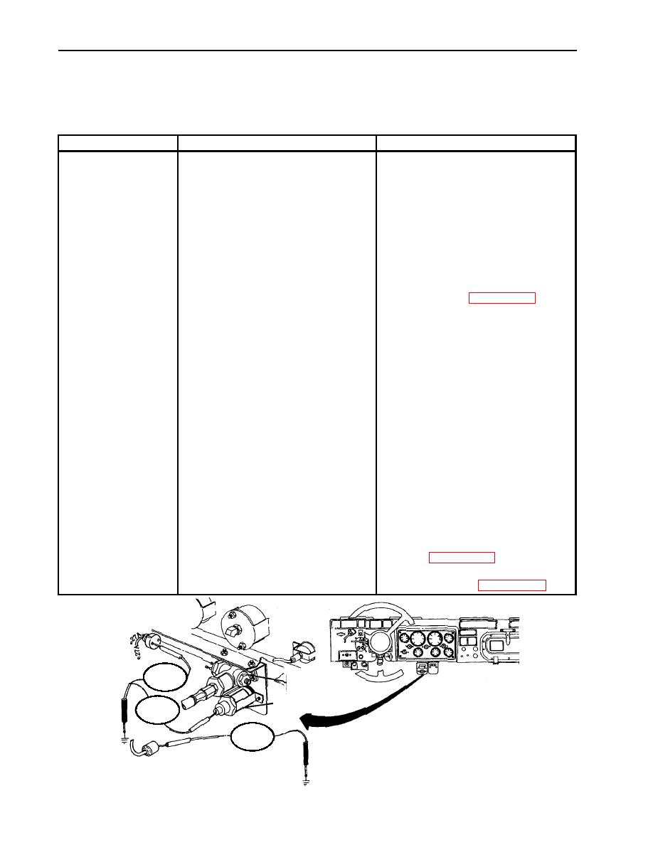
Test 1. Test lamp.
7. FRONT WHEEL
DRIVE INDICATOR
1. Place power accessory switch
LIGHT INOPERATIVE
to ON position and service
light switch to ON position.
2. Disconnect lead 27A from
indicator lamp.
3. Set multimeter to RX 1 scale.
4. Touch positive lead of
1. If continuity is present, go to test 2.
multimeter to input of
indicator lamp and negative
2. If continuity is not present, replace
lead to frame ground.
indicator lamp (WP 0118 00).
Test 2. Test front wheel drive
indicator lamp input voltage.
1. Disconnect lead 27A from
indicator lamp.
2. Set multimeter to a voltage
range that measures 24 VDC.
3. Connect multimeter positive
lead to 27A and negative lead
1. If voltage is present, reconnect and
to frame ground.
go to test 4.
2. If voltage is not present, go to
test 3.
Test 3. Test input voltage to front
wheel drive lock-in switch.
1. Remove lead 27A from pin A
of lock-in switch.
2. Connect negative lead of
multimeter to frame ground.
3. Touch positive lead of
1. If voltage is present, replace lock-in
multimeter to lead 27A.
switch (WP 0118 00).
Voltage of 24 VDC should be
present.
2. If voltage is not present, repair or
replace lead 27A (WP 0090 00).
TEST 3
FRONT WHEEL
STEP 3
DRIVE LOCK-IN
SWITCH
INDICATOR LAMP
TEST 1
STEP 3
TEST 2
STEP 3
|
|
Privacy Statement - Press Release - Copyright Information. - Contact Us |