 |
|||
|
|
|||
|
Page Title:
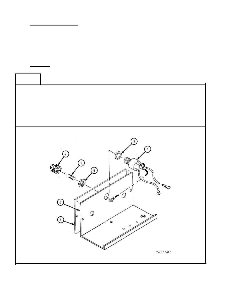
HEATER CONTROL BOX ASSEMBLY REMOVAL, REPAIR, REPLACEMENT, AND TEST - continued |
|
||
| ||||||||||
|
|
 TM 9-2320-209-34-2-3
c. Inspection and Repair.
(1) Check that all threaded parts have no stripped or damaged threads.
(2) Check that all wires have no cracked, burned or worn insulation.
(3) Check that switches have no damaged, burned or cracked terminals.
(4) Check that lamp is not burned out.
(5) Replace any damaged parts with new parts.
Assembly.
d.
FRAME 1
1.
Put indicator lamp assembly (1) with washer (2) into hole in center of control
box panel (3).
Put data plate (4) in place.
2.
3.
Put on nut (5).
Put in lamp (6) and put on lens cap (7).
4.
GO TO FRAME 2
|
|
Privacy Statement - Press Release - Copyright Information. - Contact Us |
