 |
|||
|
|
|||
|
|
|||
| ||||||||||
|
|
 TM 9-2320-209-34-2-3
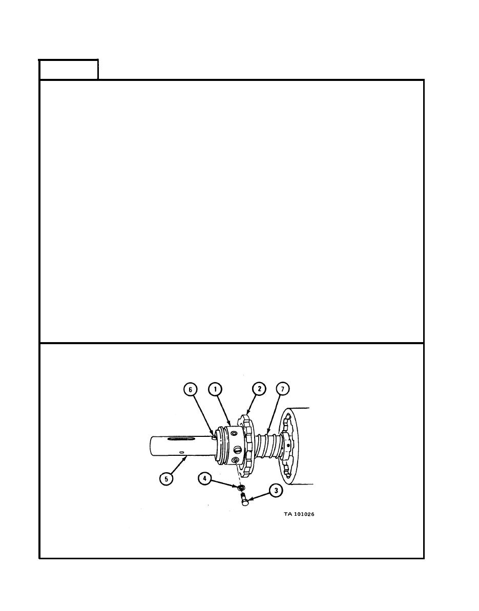
FRAME 16
Turn sleeve (1), until the tapped hole is alined with the groove in brake
1.
plate (2). Put in capscrew (3) and washer (4).
2.
Be sure that capscrew (3) goes into groove in brake plate (2). Tighten
capscrew.
Turn sleeve (1) on brake plate (2). Be sure it moves freely. If not, check
3.
capscrew (3) installation.
Try to turn brake plate (2) on drumshaft (5). If plate turns, take off brake
4.
plate and check keys (6) on drumshaft (5).
5.
Slide sleeve (1), back and forth on brake plate (2). Sleeve must hold in two
positions on clutch detent action.
Move sleeve (1) away from flange on brake plate (2). Clutch spring (7) must
6.
force brake plate back until plate is locked in position by clutch detents.
Move sleeve (1) toward flange on brake plate (2). Brake plate must force
7.
spring (7) to squeeze until detents hold plate in this second position.
Put further pressure in the same direction on sleeve (1). Sleeve must cause
8.
brake plate (2) to squeeze spring (7) another 5/32 inch.
Back off pressure on sleeve (1). Spring (7) must force brake plate (2) back
9.
until detents hold in the second position. Plate must not snap back to first
position.
10.
If sleeve (1) and brake plate (2) do not move properly for all of these
conditions, check clutch detent installation.
GO
TO FRAME 17
18-128
|
|
Privacy Statement - Press Release - Copyright Information. - Contact Us |
