 |
|||
|
|
|||
|
|
|||
| ||||||||||
|
|
 TM 9-2320-209-20-3-4
FRAME 3
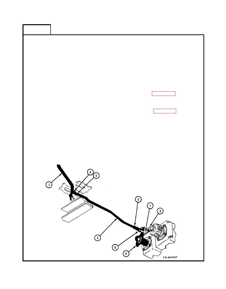
While soldier B is shifting power divider control lever (1), watch
Soldier A
1.
linkage control rod (2).
2. If power divider control lever (1) goes into all four positions and
linkage control rod (2) does not touch transfer transmission case
(3), no adjustment is needed.
3. If power divider control lever (1) does not go into all four positions
or if linkage control rod (2) touches transfer transmission case (3)
or flange (4), do steps 4 through 8.
4. Using 5/8-inch wrench, loosen nuts (5) at each end of linkage con-
trol rod (2).
5. Take off control rod assembly (2). Refer to para 19-26b.
6. Using 5/8-inch wrench, turn clevis rod ends (6) in or out as
needed and tighten nuts (5).
7. Put back control rod assembly (2). Refer to para 19-26c.
8. If needed, do steps 4 through 7 again.
NOTE
If adjustment cannot be made or if power divider shifter
shaft (7) requires adjustment, tell direct support main-
tenance.
Follow-on Maintenance Action Required:
Replace front and rear tunnel. Refer to Part 3, para
END OF TASK
19-142
|
|
Privacy Statement - Press Release - Copyright Information. - Contact Us |