 |
|||
|
|
|||
|
|
|||
| ||||||||||
|
|
 TM 9-2320-209-20-3-4
FRAME 4
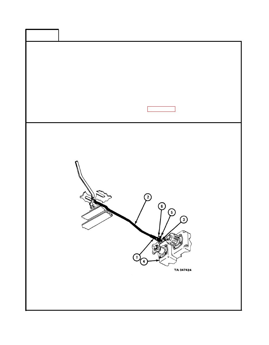
Place clevis rod end (1) of control rod assembly (2) on shifter rod (3) coming
1.
out of power divider (4).
2. Aline holes in clevis rod end (1) with hole in shifter rod (3).
3. Put pin (5) through holes in clevis rod end (1) and shifter rod (3).
4. Put cotter pin (6) in hole in pin (5).
5. Using pliers, bend open ends of cotter pin (6).
NOTE
Follow-on Maintenance Action Required:
Adjust linkage. Refer to para 19-26d.
END OF TASK
19-139
|
|
Privacy Statement - Press Release - Copyright Information. - Contact Us |