 |
|||
|
|
|||
|
|
|||
| ||||||||||
|
|
 TM 9-2320-209-20-3-4
FRAME 3
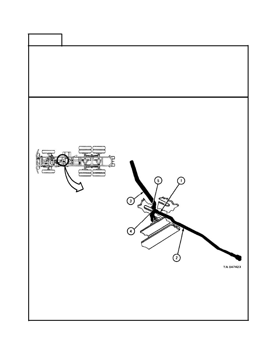
Place clevis rod end (1) of control rod assembly (2) on control lever (3).
1.
Aline holes on clevis rod end (1) with hole in control lever (3).
2.
Put pin (4) through holes in clevis rod end (1) and control lever (3).
3.
4.
Put cotter pin (5) in hole at end of pin (4).
5.
Using pliers, bend open ends of cotter pin (5).
GO
TO FRAME 4
19-138
|
|
Privacy Statement - Press Release - Copyright Information. - Contact Us |