 |
|||
|
|
|||
|
|
|||
| ||||||||||
|
|
 TM 9-2320-209-20-3-4
b.
Removal.
NOTE
Tag hydraulic lines and note the way they are
routed so they can be put back in the right place.
FRAME 1
Refer to TM 9-2320-209-10.
1.
Start engine.
NOTE
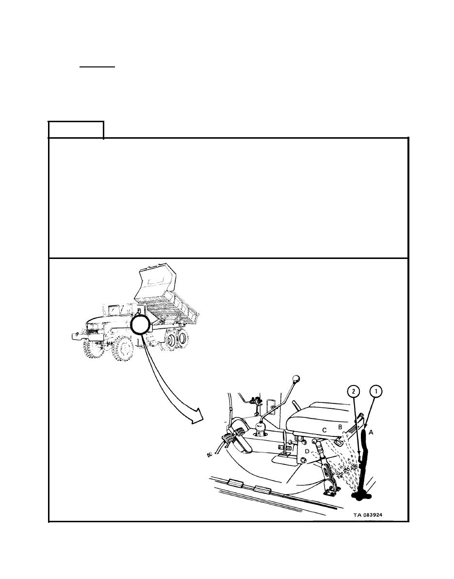
When hoist control lever (1) is put into position B,
dump body will stay up on safety braces.
2.
Put safety lock (2) in OFF position.
Put hoist control lever (1) in position B and hold for at least one minute.
3.
4.
Put hoist control lever (1) in position A.
Refer to TM 9-2320-209-10.
5.
Stop engine.
GO TO FRAME 2
|
|
Privacy Statement - Press Release - Copyright Information. - Contact Us |