 |
|||
|
|
|||
|
Page Title:
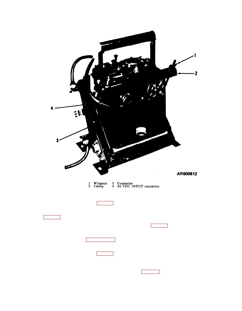
Figure 3-13. M43 detector unit installed in low profile mount. |
|
||
| ||||||||||
|
|
 TM 3-6665-225-12
Figure 3-13. M43 detector unit installed in low profile mount.
binding posts (5).
with strap (2).
(6) Position selector switch (7) to HORN
(10) Position selector switch (9, fig. 3-18) to
ON.
HORN ON.
(7) Replace left periscope (TM 9-2320-224-
(11) Perform startup and operation pro-
10).
cedures (para 2-9) to place equipment in opera-
(8) Remove two shorter straps from battery
tion.
bracket (3, fig. 3-21) mounted between periscope
i. Installing an M42 Alarm Unit, a BA3517/U
storage box (4) and jump seat (1) on right side of
Battery, a n d Refill Kit Components in an
crew compartment sponson.
Armored Command and Reconnaissance Vehicle.
(9) Remove two drawers from M 229 refill kit
(1) Perform procedures of paragraph 2-6 b.
and secure to available strap loops (6) using two
(2) Remove left periscope in driver's
straps removed in (8) above.
compartment (TM 9-2320-224-10).
(10) Loosen longer strap (5) on battery
(3) Position M42 alarm unit (1, fig. 3-20) in
bracket (3), position BA3517/U battery (2) on
bracket (6).
bracket, and secure it with strap (5).
(4) Install and latch clamping catches (3)
over knurled screws (2) on M42 alarm unit.
(11) Perform startup and operation proce-
(5) Remove protective tape from ends of
dures (para 2-9) to place equipment in operation.
cable harness wires (4) and connect wires to
3-13
|
|
Privacy Statement - Press Release - Copyright Information. - Contact Us |