 |
|||
|
|
|||
|
Page Title:
Inspection and Repair - continued |
|
||
| ||||||||||
|
|
 TM 9-2320-209-34-2-3
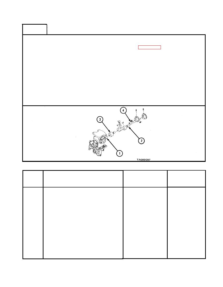
FRAME 3
NOTE
Readings must be within limits given in table 18-7.
The letter L indicates a loose fit. If readings are not
within given limits throw away part and get a new one.
1.
Measure outside diameter of speed reducer input shaft (1).
2.
Measure inside diameter of sprocket shaft bearing (2).
3.
Measure fit of bearing (2) on speed reducer input shaft (1).
4.
Measure inside diameter of sprocket shaft bracket bearing (3).
5.
Measure outside diameter of idler sprocket shaft (4).
6.
Measure fit of bearing (3) on idler shaft (4).
GO TO FRAME 4
Rear Winch (First Reduction Drive Assembly)Wear Limits
Size and Fit
Wear Limit
of New Parts
Index
(inches)
(inches)
Item/Point of Measurement
Number
None
0.749 to 0.750
1
Outside diameter of speed reducer
input shaft
None
0.001L to 0.004L
1 and 2
Fit of bearing on speed reducer
input shaft
0.762 to 0.763
0.752 to 0.753
Inside diameter of sprocket shaft
2
bracket bushing-type bearing
0.885 to 0.886
0.875 to 0.876
Inside diameter of sprocket shaft
3
bracket bushing-type bearing
None
0.001L to 0.005L
Fit of bearing on idler shaft
3 and 4
0.762 to 0.763
0.752 to 0.753
Inside diameter of sprocket shaft
4
bracket bushing-type bearing
18-101
|
|
Privacy Statement - Press Release - Copyright Information. - Contact Us |
