 |
|||
|
|
|||
|
Page Title:
FORWARD CLUTCH AND TURBINE SHAFT MAINTENANCE - continued |
|
||
| ||||||||||
|
|
 TM 9-2320-386-24-1-2
0375 00
FORWARD CLUTCH AND TURBINE SHAFT MAINTENANCE (Contd)
NOTE
Perform steps 6 through 15 to obtain clutch pack clearance.
6.
Apply oil-soluble grease to new inner seal (5) and new outer seal (4).
7.
Place piston (3) on bench with spring side facing upward.
8.
Install new outer seal (4) on piston (3). Ensure lip faces downward.
9.
Install new inner seal (5) on piston (3). Ensure lip faces downward.
10.
Apply lubricating oil to outside surface of clutch inner seal protector and inner surface of clutch
outer seal protector and position over inner seal ring (5) and outer seal ring (4).
11.
Install piston (3) on clutch housing (6) and remove clutch outer seal protector and clutch inner seal
ring protector.
12.
Install five external-tanged clutch plates (9) and five internal-splined clutch plates (8) on clutch
housing (6). Begin with external-tanged clutch plate (9).
13.
Install fourth clutch driving hub (11) on clutch housing (6) with snapring (10).
14.
For models not using a waveplate, check clutch running clearance with a clutch pack clearance
gauge.
a. While holding fourth clutch driving hub (11) against snapring (10), insert small end of clutch
pack clearance gauge between fourth clutch driving hub (11) and first internal-splined clutch
plate (8).
b. Clutch running clearance should be 0.076-0.126 in. (1.93-3.20 mm). If clearance is not within
limits, replace internal-splined clutch plates (8) and external-tanged clutch plates (9).
c. Repeat steps 7 through 13 until clearance is within limits. If clearance is still excessive, replace
with thicker piston (3). If clearance is insufficient, replace with thinner piston (3).
d. If clutch plates are within limits, remove snapring (10), fourth clutch driving hub (11), and
clutch plates as a pack and retain until further assembly.
15.
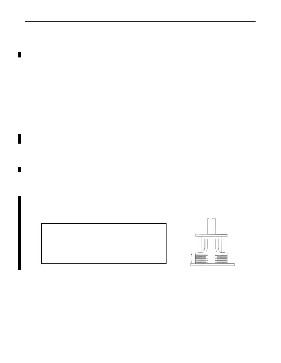
For models using a waveplate, check clutch running clearance by performing the stack method.
a. Stack forward clutch plates.
b. Apply 980-1020 lb. (4359-4537 N) of pressure and record dimension X.
c. Use table below to select forward clutch piston. Use the parts measured with
selected piston in forward clutch assembly.
DIMENSION X
USE PISTON
0.984 - 1.010 in. (24.99 - 25.65 mm)
EF
1.010 - 1.046 in. (25.65 - 26.57 mm)
E
1.046 - 1.072 in. (26.57 - 27.23 mm)
DE
X
16.
Install sixteen springs (2) and spring retainer (7) on piston (3).
17.
Using compression tool and arbor press, compress spring retainer (7) until snapring groove appears
on clutch housing (6).
18.
Install snapring (1) on clutch housing (6) and remove compression tool.
19.
Apply oil-soluble grease to thrust bearing races (15) and (13) and bearing (14).
20.
Install thrust bearing race (15), bearing (14), and thrust bearing race (13) on clutch housing (6).
21.
Install forward clutch hub (12) on forward clutch housing (6).
22.
Beginning with external-tanged clutch plate (9), install five external-tanged clutch plates (9) and
five internal-splined clutch plates (8) on clutch housing (6).
23.
Install fourth clutch driving hub (11) on clutch housing (6) with snapring (10).
Change 1
0375 00-10
|
|
Privacy Statement - Press Release - Copyright Information. - Contact Us |
