 |
|||
|
|
|||
|
Page Title:
GOVERNOR REPLACEMENT - continued |
|
||
| ||||||||||
|
|
 TM 9-2320-386-24-1-2
0326 00
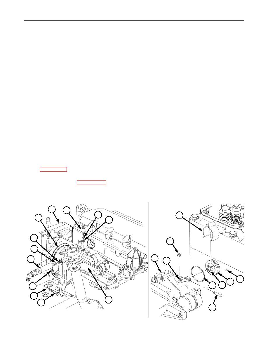
GOVERNOR REPLACEMENT (Contd)
INSTALLATION
1.
Install new O-ring (5) on outlet fitting (4).
2.
Install new check valve (6) and outlet fitting (4) on governor (7).
3.
Install new O-ring (12) on inlet fitting (11).
4.
Install new check valve (1) and inlet fitting (11) on governor (7).
5.
Position new O-ring (2) on governor (7), and install governor (7) on front housing (3) with three
sleeves (10), washers (9), and screws (8).
6.
Install new O-ring (17) on sleeve (15).
7.
Install clevis (19) on link (16) with pin (18) and new retaining ring (20).
8.
Using soft-jawed pliers, slide sleeve (15) from cylinder head (14) into governor (7).
9.
Install clip (13) on sleeve (15).
10.
Connect fuel inlet hose (24) to elbow (21).
11.
Install new O-ring (22) and fuel supply line (23) to governor (7).
12.
Install bracket (32), with accelerator cable (28) and throttle control cable (29) attached, on
governor (7) with two washers (30) and screws (31).
13.
Install bracket (27), with throttle control cable (29) and accelerator cable (28) attached, on throttle
lever (41) with washer (40) and nut (39).
14.
Install spring (26) on brackets (27) and (25).
15.
Three leads 54A (36), 770-R (37), and GND (35), two new lockwashers (33), and nuts (34) will be
installed on fuel shutoff solenoid (38) when performing follow-on task, Fuel Setting Adjustment
16.
Install ratio control and governor oil line (WP 0051 00).
17.
Adjust fuel setting (WP 0323 00).
18.
Connect battery ground cable (WP 0121 00).
19.
Adjust governor low-idle speed (WP 0052 00).
3
4
5
13
2
6
1
20
12
7
11
19
~
14
15
16
17
10
9
7
8
18
0326 00-6
|
|
Privacy Statement - Press Release - Copyright Information. - Contact Us |