 |
|||
|
|
|||
|
Page Title:
FUEL SETTING ADJUSTMENT - continued |
|
||
| ||||||||||
|
|
 TM 9-2320-386-24-1-2
0323 00
FUEL SETTING ADJUSTMENT (Contd)
NOTE
Refer to valve cover information plate for fuel setting dimension
(FULL LOAD STATIC FUEL).
23. Determine the fuel setting dimension of engine.
a. If horizontal dial indicator is 0.25 mm of the specified fuel setting dimension of engine, go to
step 28.
b. If horizontal dial indicator is not 0.25 mm of the specified fuel setting dimension of engine, go
to step 24.
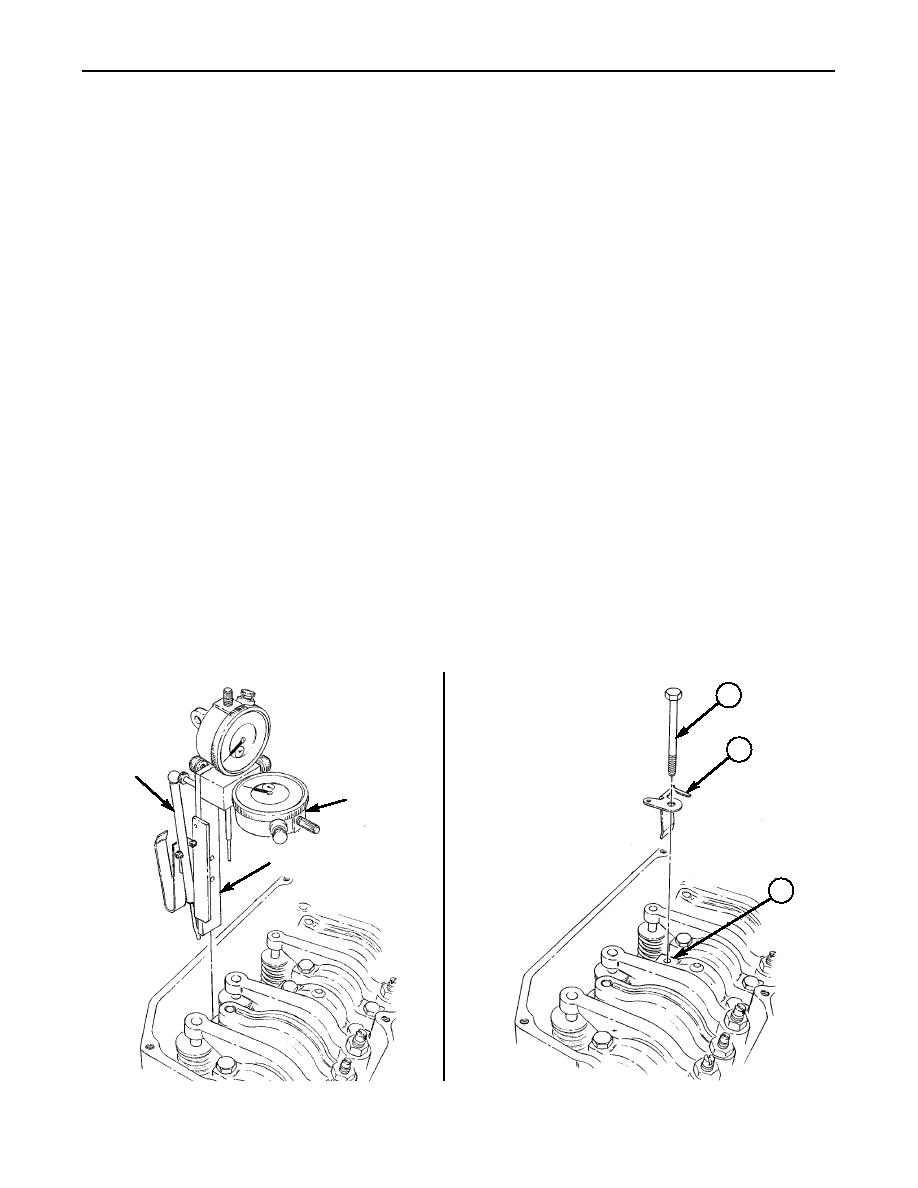
24. Remove screw (1) and anchor (2) from rocker arm assembly (3).
25. Using adjusting tool, loosen locknut (6) and adjust setscrew (4) on fuel setting clamp (5) until
horizontal dial indicator reads within 0.25 mm of the specified fuel setting dimension of engine.
NOTE
Thread pull can cause adjustment to change when locknut is
tightened and readjustment may be necessary.
26. Tighten locknut (6) on fuel setting clamp (5) with adjusting tool.
27. Install anchor (2) and screw (1) on rocker arm assembly (3). Tighten screw (1) 18-22 lb-ft
(24-30 Nm).
28. Remove fuel setting wedge from between sleeve (7) and fuel setting pin.
29. Remove fuel setting pin from pin (8).
30. Remove holding fixture with dial indicators from No. 1 injector by pressing top ball on pivot arm
fully and pulling holding fixture straight up. Release pivot arm after removal.
31. Using soft-jawed pliers, slide sleeve (10) from cylinder head (11) into governor (12).
32. Install clip (9) on sleeve (10).
33. Install fuel shutoff solenoid (WP 0050 00).
34. Install valve cover (WP 0028 00).
1
2
PIVOT
ARM
HORIZONTAL
DIAL INDICATOR
HOLDING FIXTURE
3
0323 00-8
|
|
Privacy Statement - Press Release - Copyright Information. - Contact Us |