 |
|||
|
|
|||
|
Page Title:
FUEL INJECTOR TIMING MAINTENANCE - continued |
|
||
| ||||||||||
|
|
 TM 9-2320-386-24-1-2
0322 00
FUEL INJECTOR TIMING MAINTENANCE (Contd)
7.
Clean top surfaces of injector tappets (1) with lint-free cloth.
NOTE
No. 1 piston is on compression stroke if intake and exhaust valves
are closed and rocker arms can be moved by hand.
No. 1 piston is on exhaust stroke if intake and exhaust valves are
open and rocker arms cannot be moved by hand.
Set timing for No. 1 injector last. This will be correct position to
check and adjust fuel setting later.
8.
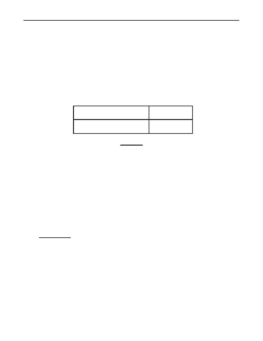
Position No. 1 piston at TC and make identification for the correct stroke (compression or exhaust).
Refer to table 1 for correct injector sequence.
Table 1. Crankshaft Positions for Fuel Timing.
Check/adjust with No. 1
Injectors 3-5-6
piston on TC compression stroke
Check/adjust with No. 1
Injectors 1-2-4
piston on TC exhaust stroke
9.
Press top ball on pivot arm of holding fixture fully and hold.
CAUTION
Bottom contact point on pivot arm of holding fixture must clear
end of rack bar when inserted into engine. Failure to do so will
cause damage to equipment and result in an inaccurate reading.
10.
While keeping top ball on pivot arm pressed, insert holding fixture with dial indicators at injector
to be timed so stabilizing blade seats against intake valve spring (5), and spring clip seats against
inside of air intake manifold (6).
11.
Push down on holding fixture and listen for a "snap" sound to ensure holding fixture is seated
against injector base.
12.
Release top ball on pivot arm of holding fixture. Ensure pivot arm contacts face of rack bar (4) and
indicator contact point contacts injector tappet (1).
NOTE
Refer to valve cover information plate for fuel timing dimension.
13.
Determine the fuel timing dimension of engine. The set block for calibration measures 62.0 mm. To
determine what the vertical dial indicator should read, subtract 62.0 mm from the fuel timing
dimension on valve cover.
xx.xx mm
Fuel timing dimension on valve cover
62.00 mm
Set block for calibration
=
xx.xx mm
Vertical dial indicator reading
14.
Ensure vertical dial indicator matches the answer from step 13 0.05 mm.
a. If vertical dial indicator does match the answer from step 13 0.05 mm, timing is correct and no
adjustment is necessary. Go to step 18.
b. If vertical dial indicator does not match the answer from step 13 0.05 mm, timing is incorrect
and adjustment is necessary. Go to step 15.
15.
Loosen jamnut (3) on push rod adjustment screw (2).
16.
Turn push rod adjustment screw (2) until reading on vertical dial indicator matches answer from
step 13 0.05 mm.
NOTE
Thread pull can cause adjustment to change when jamnut is
tightened, and readjustment may be necessary.
Tighten jamnut (3) on push rod adjustment screw (2) 13-23 lb-ft (18-31 Nm).
17.
0322 00-4
|
|
Privacy Statement - Press Release - Copyright Information. - Contact Us |