 |
|||
|
|
|||
|
Page Title:
CYLINDER HEAD (IN-VEHICLE) MAINTENANCE - continued |
|
||
| ||||||||||
|
|
 TM 9-2320-386-24-1-2
0302 00
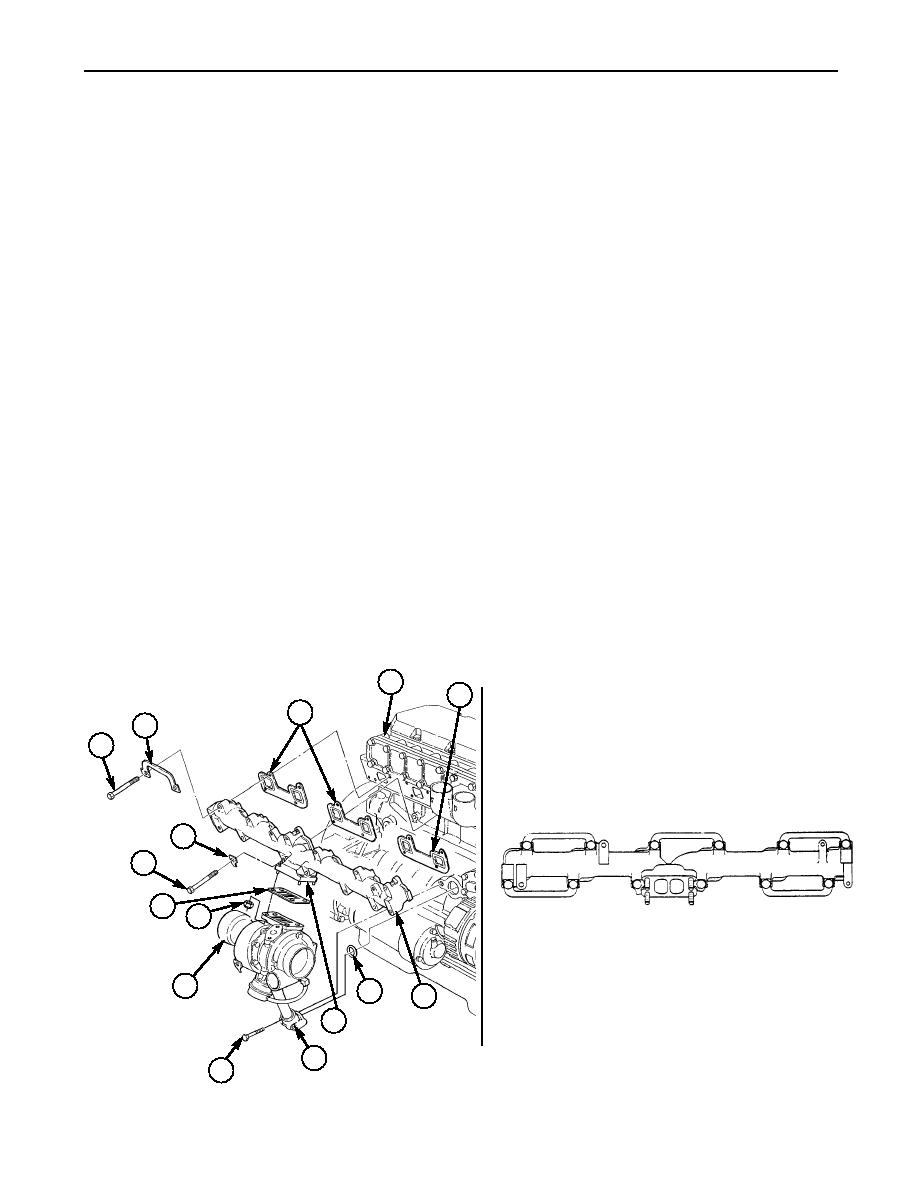
CYLINDER HEAD (IN-VEHICLE) MAINTENANCE (Contd)
33.
Apply antiseize compound to threads of screws (1).
34.
Install three new gaskets (3) and exhaust manifold (5) on engine (4) with five new retaining rings (2),
new retaining ring (13), and twelve screws (1).
Tighten screws (1) 2-4 lb-ft (3-5 Nm) in sequence shown.
35.
36.
Tighten screws (1) 29-37 lb-ft (39-50 Nm) in sequence shown.
37.
Bend tabs of retaining rings (2) and (13) over heads of screws (1).
38.
Install new O-ring (6) in groove of oil drain tube (8).
39.
Install new gasket (12) and turbocharger (10) on exhaust manifold (5), apply antiseize compound to
studs (7), and install four new locknuts (11). Tighten locknuts (11) 36-44 lb-ft (49-60 Nm).
40.
Install oil drain tube (8) on engine (4) with two screws (9).
41.
Install new O-ring (17) and elbow (16) on fitting (18) of oil cooler (19).
42.
Install new O-ring (15) on elbow (16).
43.
Install new gasket (20) and oil inlet tube (14) on turbocharger (10) with two washers (21) and
screws (22).
44.
Connect oil inlet tube (14) to elbow (16).
45.
Install two new gaskets (24) and flexpipe (28) on turbocharger (10) and elbow pipe (27) with two
clamps (23), screw (25), and two nuts (26).
46.
Install hose (30) on water regulator housing (36) and tighten clamp (31).
47.
Install new gasket (29) and water regulator housing (36) on engine (4) with two screws (32).
48.
Install mounting bracket (35) on water regulator housing (36) with washer (33) and screw (34).
49.
Connect personnel heater tube (40) to connector (39).
50.
Connect tube (37) to elbow (38).
51.
Install personnel heater tube (40) and hose (43) on engine (4) with three clamps (42) and screws (41).
4
3
3
2
1
8
1
5
9
13
12
4
1
3
6
7
2
11
10
12
11
10
TORQUE SEQUENCE
6
5
7
8
9
0302 00-26
|
|
Privacy Statement - Press Release - Copyright Information. - Contact Us |
