 |
|||
|
|
|||
|
Page Title:
TRANSMISSION SELECT LEVER MAINTENANCE - continued |
|
||
| ||||||||||
|
|
 TM 9-2320-386-24-1-1
0134 00
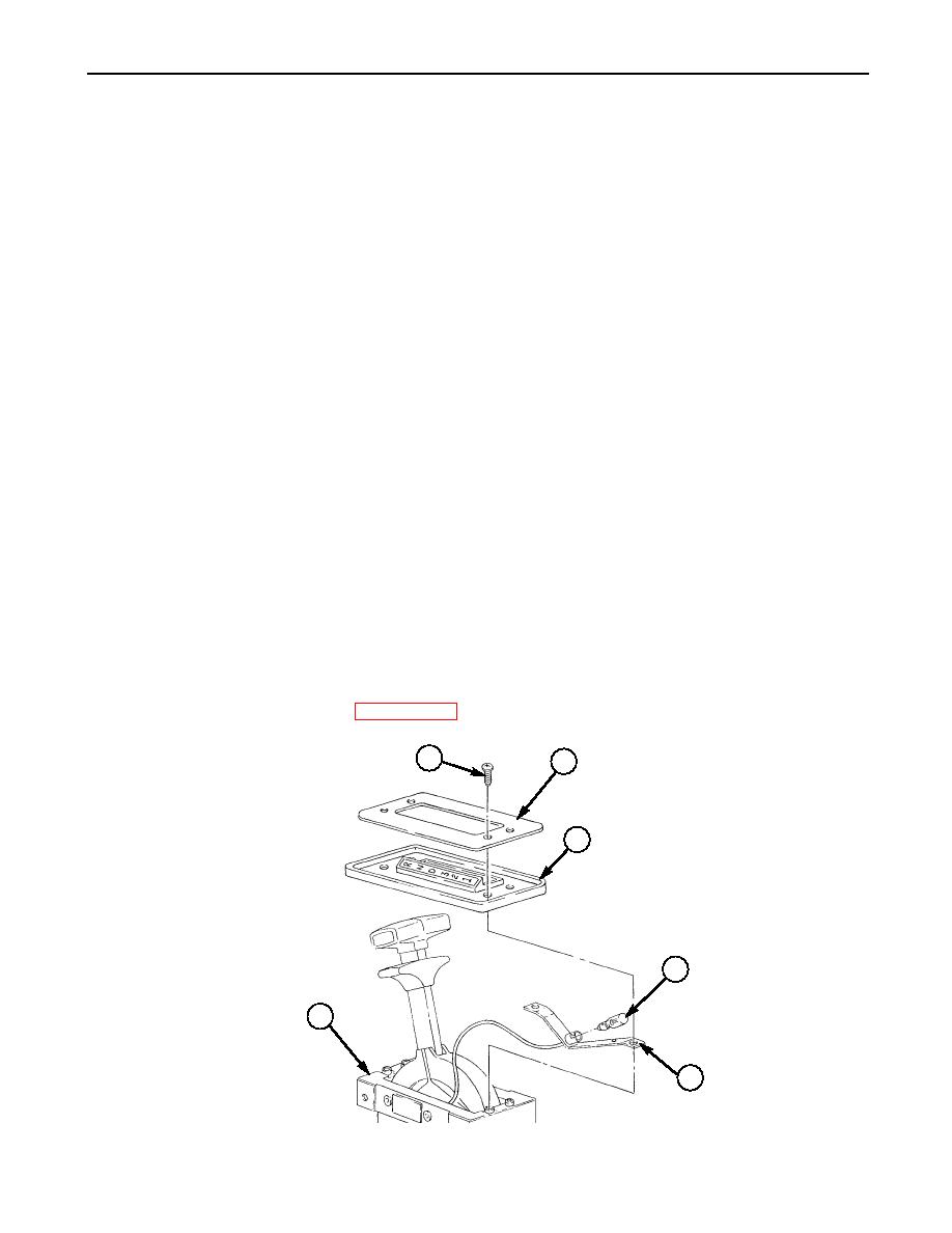
TRANSMISSION SELECT LEVER MAINTENANCE (Contd)
ASSEMBLY
1.
Install lamp (4) on bracket (5).
2.
Position bracket (5) on select lever (6).
3.
Install bracket (5), cover seal (3), and cover plate (2) on select lever (6) with four screws (1).
INSTALLATION
1.
Install spacer (17), shift cable (11), and clamp (18) on select lever (6) with two screws (12), new
lockwashers (19), and nuts (20).
2.
Install new lockwasher (15), ground lead 99A (14), screw (13), and new plain-assembled nut (16) on
select lever (6).
3.
Install connecting link (8) on shift cable (11).
NOTE
Perform step 4 if additional clearance is required when adjusting shift cable.
4.
Remove nut (10) and screw (28) from select lever (6).
5.
Place select lever (6) and manual control lever on transmission in first gear position and check that
connecting link (8) aligns with hole in select lever (6). Adjust connecting link (8) in or out on shift
cable (11) if necessary.
6.
Move select lever (6) and manual control lever to full rear position R (reverse) on transmission and
check that connecting link (8) aligns with hole in select lever (6). Adjust connecting link (8) in or out
on shift cable (11) if necessary and tighten jamnut (9).
7.
Install shift cable (11) on select lever (6) with new lockpin (7).
8.
If removed, install screw (28) and nut (10) on select lever (6).
9.
Position select lever (6) on two supports (23) and install with four new lockwashers (27) and
screws (26).
10.
Connect wiring harness plug with lead 40 (22) to connector (21).
11.
Install two side plates (24) on supports (23) with twelve screws (25).
12.
Connect battery ground cable (WP 0121 00).
1
2
3
4
6
5
0134 00-4
|
|
Privacy Statement - Press Release - Copyright Information. - Contact Us |
