 |
|||
|
|
|||
|
Page Title:
ACCELERATOR PEDAL, BRACKETS, AND ROD MAINTENANCE - continued |
|
||
| ||||||||||
|
|
 TM 9-2320-361-24-1
0070 00
ACCELERATOR PEDAL, BRACKETS, AND ROD MAINTENANCE (Contd)
INSTALLATION (Contd)
10.
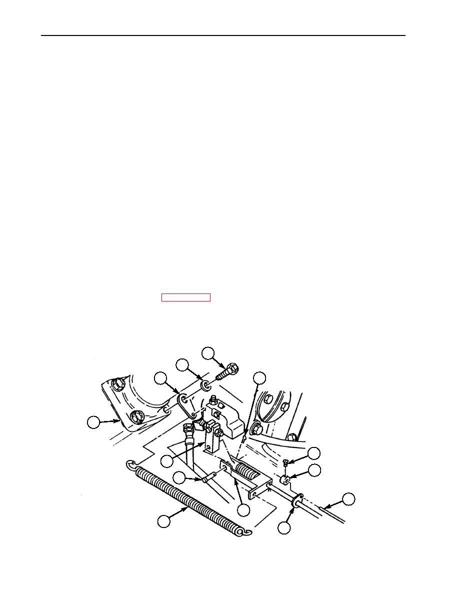
Connect swivel (9) to pump lever (12) with pin (11) and new cotter pin (4).
11.
Position control wire (7) through flange on accelerator rod (8) and install connector (6) and
screw (5) on control wire (7). Do not tighten. Position connector (6) 0.125 in. (0.32 mm) from flange
on accelerator rod (8) and tighten screw (5).
12.
Install throttle return clip (1) on steering gear housing (13) with washer (2) and screw (3).
13.
Install spring (10) on throttle return clip (1) and swivel (9).
ADJUSTMENT
1.
Remove locknut (15) from threaded stud (16) and remove threaded stud (16) of ball joint (18) from
lever (17).
2.
Loosen nut (19) on accelerator rod (14).
NOTE
Rod is shortened by turning ball joint clockwise on rod and
lengthened by turning ball joint counterclockwise on rod.
3.
Shorten or lengthen accelerator rod (14) until threaded stud (16) of ball joint (18) will freely slide
into hole of lever (17).
4.
Install locknut (15) on threaded stud (16) and tighten locknut (15).
5.
Tighten nut (19) on accelerator rod (14).
6.
Connect battery ground cable (WP 0126 00).
7.
Start engine (TM 9-2320-361-10) and check throttle for proper operation.
8.
Lower and secure hood (TM 9-2320-361-10).
9.
Release parking brake and remove wheel chocks (TM 9-2320-361-10).
3
2
1
4
13
5
12
6
11
7
9
10
8
0070 00-6
|
|
Privacy Statement - Press Release - Copyright Information. - Contact Us |