 |
|||
|
|
|||
|
Page Title:
FUEL BURNING PERSONNEL HEATER REMOVAL, REPAIR, TEST, AND REPLACEMENT - continued |
|
||
| ||||||||||
|
|
 TM 9-2320-209-34-2-3
FRAME 6
NOTE
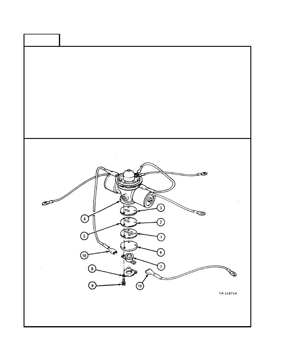
Put gasket (1), orifice plate (2), and gasket (3) on
cover plate (4) as shown. Put orifice plate and
gasket assembly (5) on fuel control valve (6) as
shown.
1.
Put gasket (1), orifice plate (2), and gasket (3) on cover plate (4).
2.
Put orifice plate and gasket assembly (5) on fuel control valve body (6).
Put thermostat (7) and clamp (8) on orifice plate and gasket assembly (5).
3.
4.
Screw in and finger tighten three screws (9).
Tighten three screws evenly,
tightening each one a little at a time.
5.
Slide two electrical leads (10) on terminals.
GO TO FRAME 7
21-84
|
|
Privacy Statement - Press Release - Copyright Information. - Contact Us |