 |
|||
|
|
|||
|
|
|||
| ||||||||||
|
|
 TM 9-2320-209-34-2-3
FRAME 2
1.
Replace hydraulic hoist control linkage. Refer to
TM 9-2320-209-20.
2.
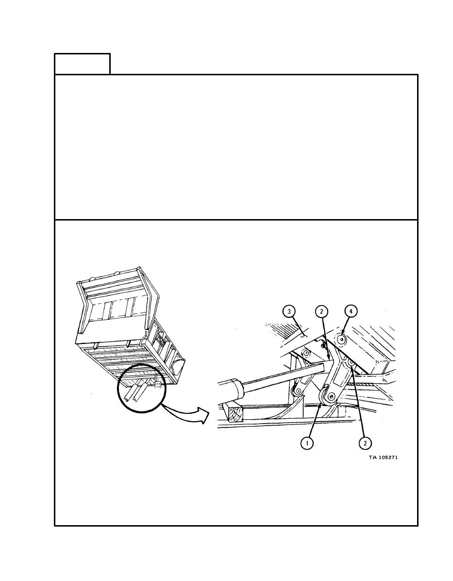
Slide two roller arm assemblies (1) onto crosshead (2).
Soldier A 3.
Start engine and raise dump body to raise crosshead (2) with
roller arm assemblies (1) . Refer to TM 9-2320-209-10.
Soldier B 4.
Align holes in roller arm assemblies (1) with holes in dump
body (3).
NOTE
A jack may be needed to finish aligning holes.
Drive pin (4) through dump body (3) and roller arm assemblies
5.
(1). Align screw holes in pins with screw holes in dump body.
GO TO FRAME 3
18-187
|
|
Privacy Statement - Press Release - Copyright Information. - Contact Us |