 |
|||
|
|
|||
|
|
|||
| ||||||||||
|
|
 TM 9-2320-209-34-2-3
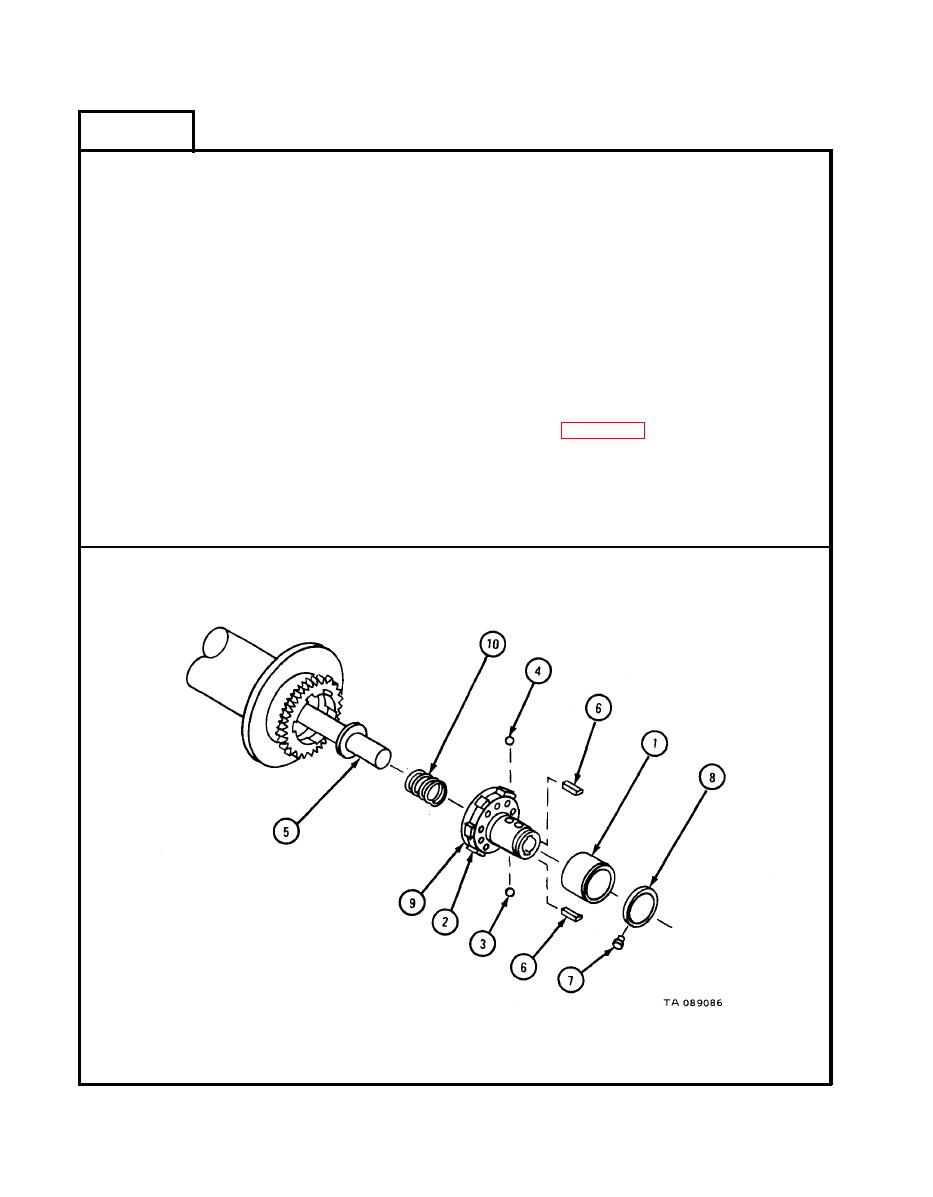
FRAME 18
1.
Slide clutch spacer (1) toward gear part of brake plate assembly (2).
Turn clutch spacer (1), until ball (3) can be taken out of 9/16-inch diameter
2.
hole in sleeve.
Turn clutch spacer (1) halfway around, and take out ball (4).
3.
Slide clutch spacer (1) and brake plate assembly (2) off shaft (5).
4.
Take off two keys (6) from shaft (5).
5.
Take out four rivets (7) holding stop ring (8) to brake plate assembly (2).
6.
Take apart clutch spacer (1) and stop ring (8) from brake plate assembly (2).
7.
NOTE
Do not take off brake lining (9) from brake plate
assembly unless it is damaged. Refer to para 18-5e
for inspection procedures.
Take out rivets to take apart lining from brake plate assembly.
8.
Slide compression spring (10) off shaft (5).
9.
GO TO FRAME 19
18-90
|
|
Privacy Statement - Press Release - Copyright Information. - Contact Us |
