 |
|||
|
|
|||
|
Page Title:
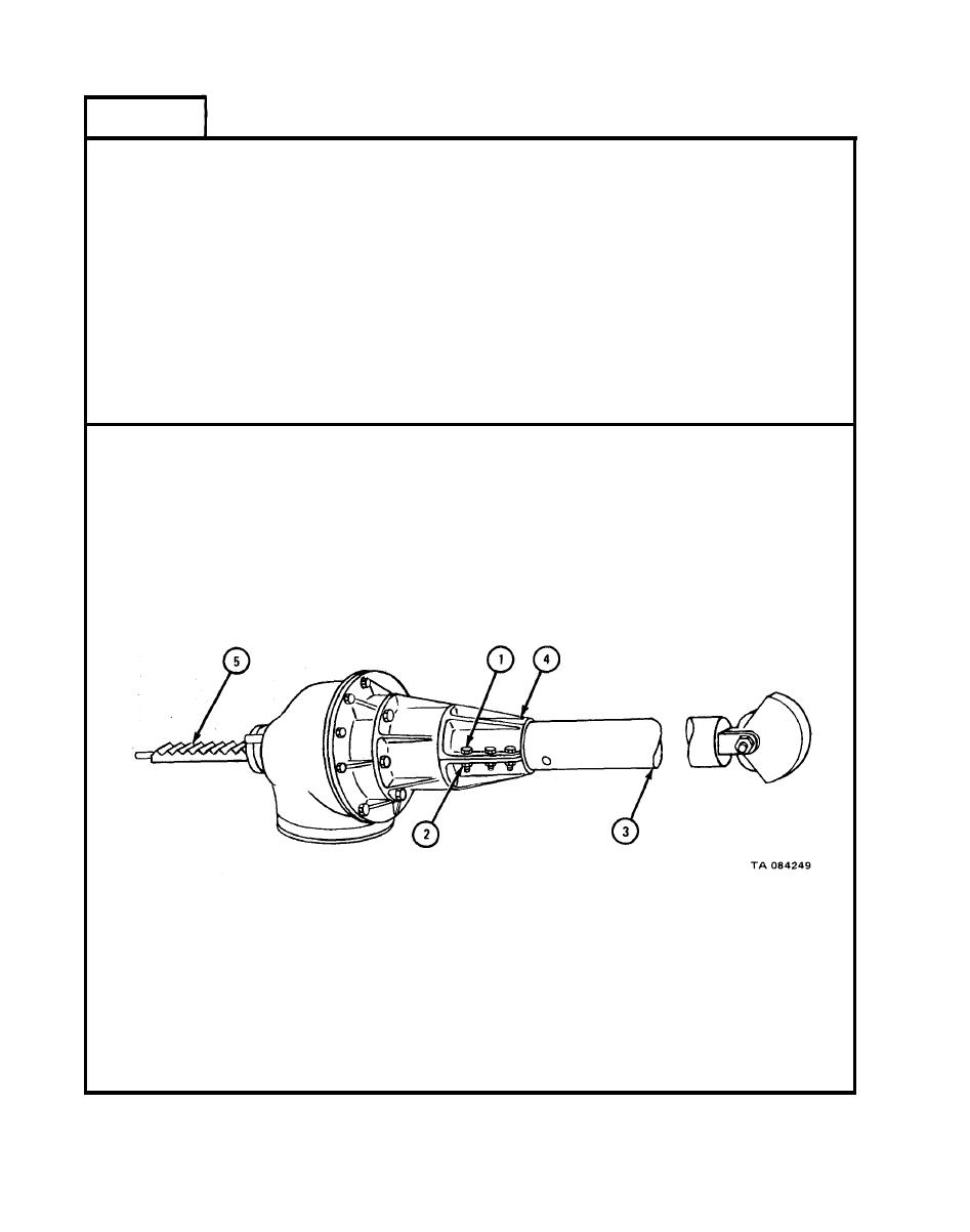
INTEGRAL DERRICK AND DERRICK SHEAVE ASSEMBLY REMOVAL, REPAIR, AND REPLACEMENT - continued |
|
||
| ||||||||||
|
|
 TM 9-2320-209-34-2-2
FRAME 2
1.
Tighten three capscrews (1) and hex nuts (2) to clamp derrick assembly (3)
and derrick tube base (4).
2.
Using boring machine, feed rack bar (5) back into derrick assembly (3) .
Refer to Raising, Leveling, and Lowering the Derrick Tube, TM 9-2320-209-10.
3.
Using boring machine, place derrick assembly into resting position on cradle.
Refer to Raising, Leveling, and Lowering the Derrick Tube, TM 9-2320-209-10.
NOTE
Follow-on Maintenance Action Required:
Remove wheel chocks and raise outrigger arms. Refer
to TM 9-2320-209-10.
END OF TASK
17-714
|
|
Privacy Statement - Press Release - Copyright Information. - Contact Us |
