 |
|||
|
|
|||
|
Page Title:
INTERMEDIATE CASE AND GEAR ASSEMBLY REMOVAL, REPAIR, REPLACEMENT AND ADJUSTMENT (TRUCK M764) - continued |
|
||
| ||||||||||
|
|
 TM 9-2320-209-34-2-2
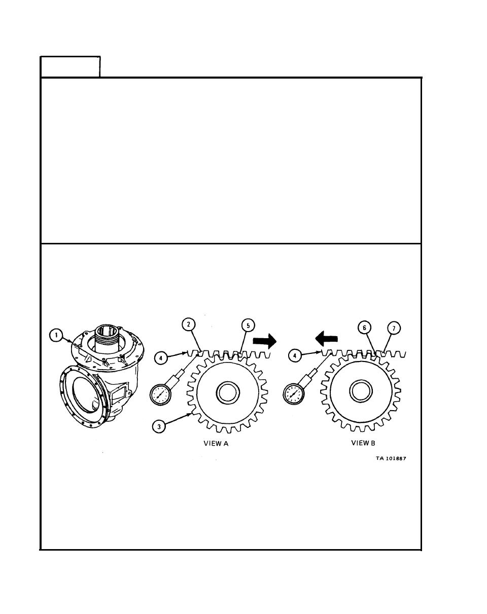
FRAME 3
Working through boring case inspection hole (1), mount dial indicator on
1.
housing and set stem against side of rack drive gear tooth (2) as shown.
NOTE
When measuring backlash, make sure second reduction drive
pinion (3) does not turn. If pinion turns, backlash readings
will be wrong.
2.
Turn rack drive gear (4) away from dial indicator until rack drive gear tooth
(5) touches pinion tooth (6) as shown in view A.
Set dial indicator to read 0.
3.
Turn rack drive gear (4) toward dial indicator until rack drive gear tooth (7)
4.
touches other side of pinion tooth (6) as shown in view B. Note reading
on dial indicator.
IF
READING ON DIAL INDICATOR IS NOT 0.008 TO 0.030 INCH, GO TO FRAME 4.
IF
READING ON DIAL INDICATOR IS 0.008 TO 0.030 INCH, END OF TASK
17-564
|
|
Privacy Statement - Press Release - Copyright Information. - Contact Us |
