 |
|||
|
|
|||
|
Page Title:
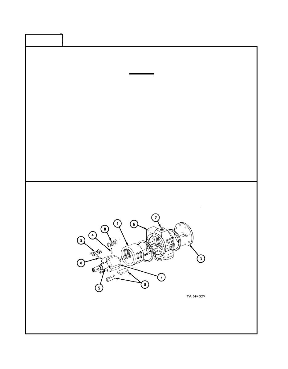
CENTRIFUGAL PUMP REPAIR (TRUCKS M49A1C, M49A2C, M50A1, M50A2, AND M50A3) - continued |
|
||
| ||||||||||
|
|
 TM 9-2320-209-34-2-2
FRAME 3
Find punch marks made at time of diassembly. Put liner (1) in casing (2).
1.
Be sure pin hole in liner is at top of pump.
CAUTION
Replacement rotors are bronze with stainless steel
shaft. This makes the pump assembly suitable for
either fuel or water tank bodies. If rotor is not
replaced, look to see if rotor is bronze or cast iron.
If rotor is cast iron, put a tag on reading "fuel
tank truck only". Cast iron and water makes rust
and can damage pump.
2.
Place casing (2) on a bench with outboard head (3) down. Place a pushrod
pin (4) in each of the two holes through the rotor (5). Put rotor in pump
liner (1).
Place casing (2) on bypass valve (6) side, while holding rotor shaft (5)
3.
against outboard head (3).
4.
Turn rotor (5) by hand. As slot (7) reaches top, put in vanes (8). Be
sure beveled edge is against liner (1) and pressure grooves on right side
of vane.
GO TO FRAME 4
17-244
|
|
Privacy Statement - Press Release - Copyright Information. - Contact Us |
