 |
|||
|
|
|||
|
Page Title:
Assembly and Adjustment - continued |
|
||
| ||||||||||
|
|
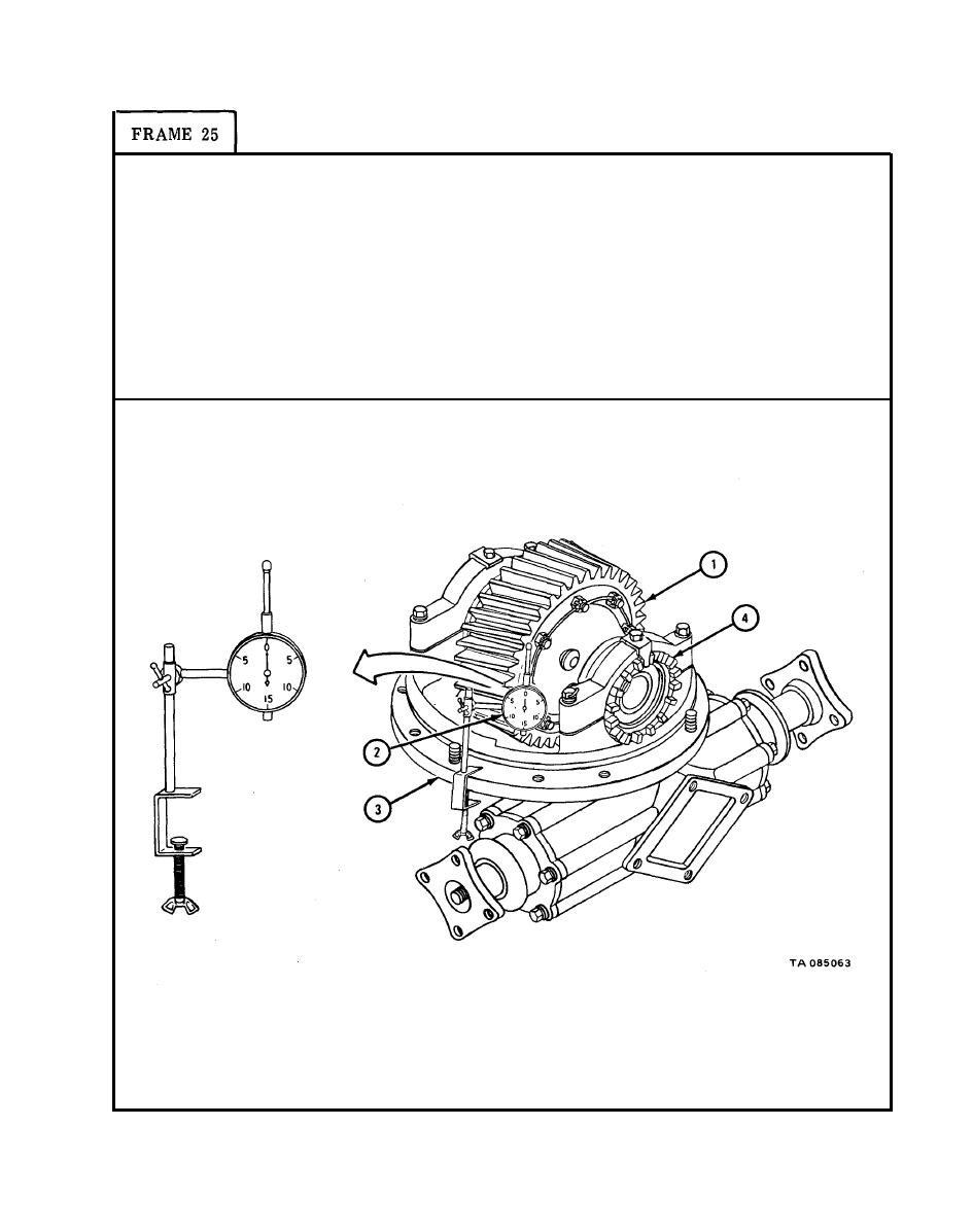 TM 9-2320-209-34-2-1
Turn helical drive gear (1) several times to seat bearings.
1.
2.
Place dial indicator (2) on carrier flange (3) so plunger is against side face of
helical gear (1).
3.
Push and pull on helical drive gear (1) and check reading on dial indicator (2).
4.
Using spanner wrench, tighten two adjusting nuts (4) a little at a time. Do
step 3 again until dial indicator (2) reading is 0.000 inch.
5.
Turn helical drive gear (1) one full turn. Check that runout on dial
indicator (2) shows 0.008 inch or less.
GO
TO FRAME 26
10-93
|
|
Privacy Statement - Press Release - Copyright Information. - Contact Us |
