 |
|||
|
|
|||
|
Page Title:
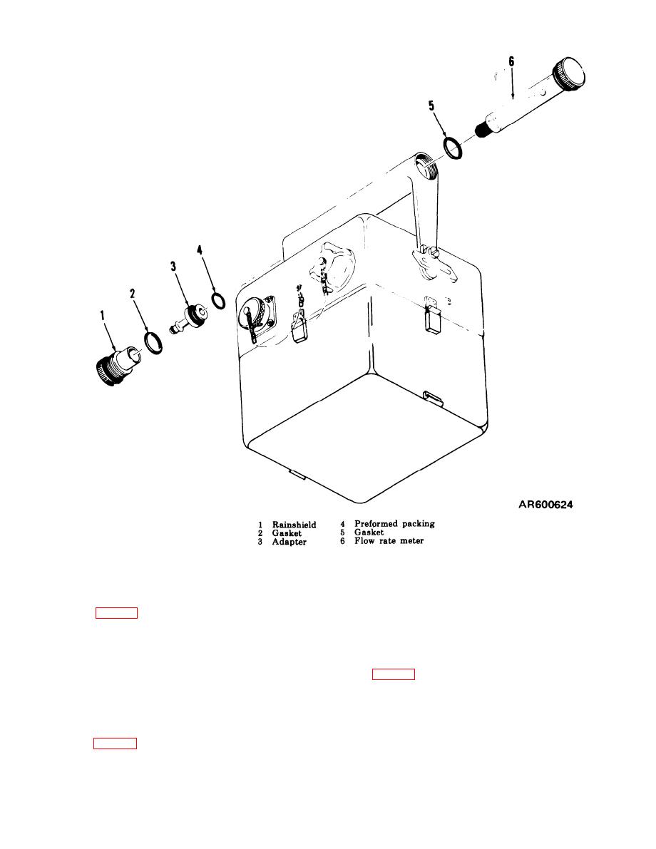
Figure 4-2. RAINSHIELD assembly and flow rate meter components. |
|
||
| ||||||||||
|
|
 TM 3-6665-225-12
Figure 4-2. RAINSHIELD assembly and flow rate meter components.
412. Selector Switch Knob
and then from chassis assembly (1).
b. Remove packing (2).
c. Replace screw (3) by reversing order of dis-
a. Rotate knob (7) fully clockwise.
assembly (a and b above).
b. Loosen two setscrews (6) and remove knob
(7) from selector switch shaft.
414. ALARM-RED Indicator Lens and Lamp
c. Position replacement knob (7) on selector
switch shaft so that its pointer is at HORN ON.
a. Unscrew lens (4) and remove lamp (5) after
d. Tighten two setscrews (6) to secure knob (7)
pressing it in and turning it counterclockwise.
to shaft.
b. Replace defective lamp (5) or lens (4) by
reversing order of removal.
413. Knurled Screws
a. Unscrew defective screw (3) from housing (8)
4-3
|
|
Privacy Statement - Press Release - Copyright Information. - Contact Us |