 |
|||
|
|
|||
|
Page Title:
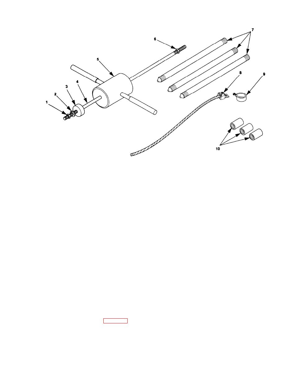
Figure 2- 5. Ground Rod, Grounding Strap, and Sldie Hammer. |
|
||
| ||||||||||
|
|
 TM 9-6115-663-13&P
(1) Install impact disk (3) on rod (4). Tighten impact disk to end of threads on rod (4).
(2) Install lock washer (2) and nut (l). Tighten nut (1) and lock washer (2) securely against
impact disk (3).
NOTE
Nut (6) must be removed before positioning slide hammer.
(3) Position hammer (5) on rod (4). Install nut (6) tighten to end of threads on rod (4).
Connect ground rod coupling (10) tO ground rod (7) screw slide hammer into coupling (10).
b.
Make sure that slide hammer rod (4) seats on ground rod (7).
Drive ground rod into ground until coupling is just above surface.
c.
Remove slide hammer assembly and install another section of ground md (7).
d.
Install another coupling (10) and the slide hammer assembly. Drive ground rod down until new
e.
coupling is just above ground surface.
f.
Repeat steps d and e until ground rod has been driven eight feet or deeper, providing an effective
ground.
Connect clamp (9) and ground cable (8) to ground rod (7) and tighten clamp screw.
g.
Connect ground cable (8, figure 2-5) as follows.
h.
(1) Remove and retain wing nut (1 figure 2-4) and washer (2) from trailer ground stud (4) and
install ground cable terminal (3) to ground stud (4).
|
|
Privacy Statement - Press Release - Copyright Information. - Contact Us |
