 |
|||
|
|
|||
|
Page Title:
INSTRUMENT PANEL CONTROLS AND INDICATORS |
|
||
| ||||||||||
|
|
 TM 9-2320-391-10
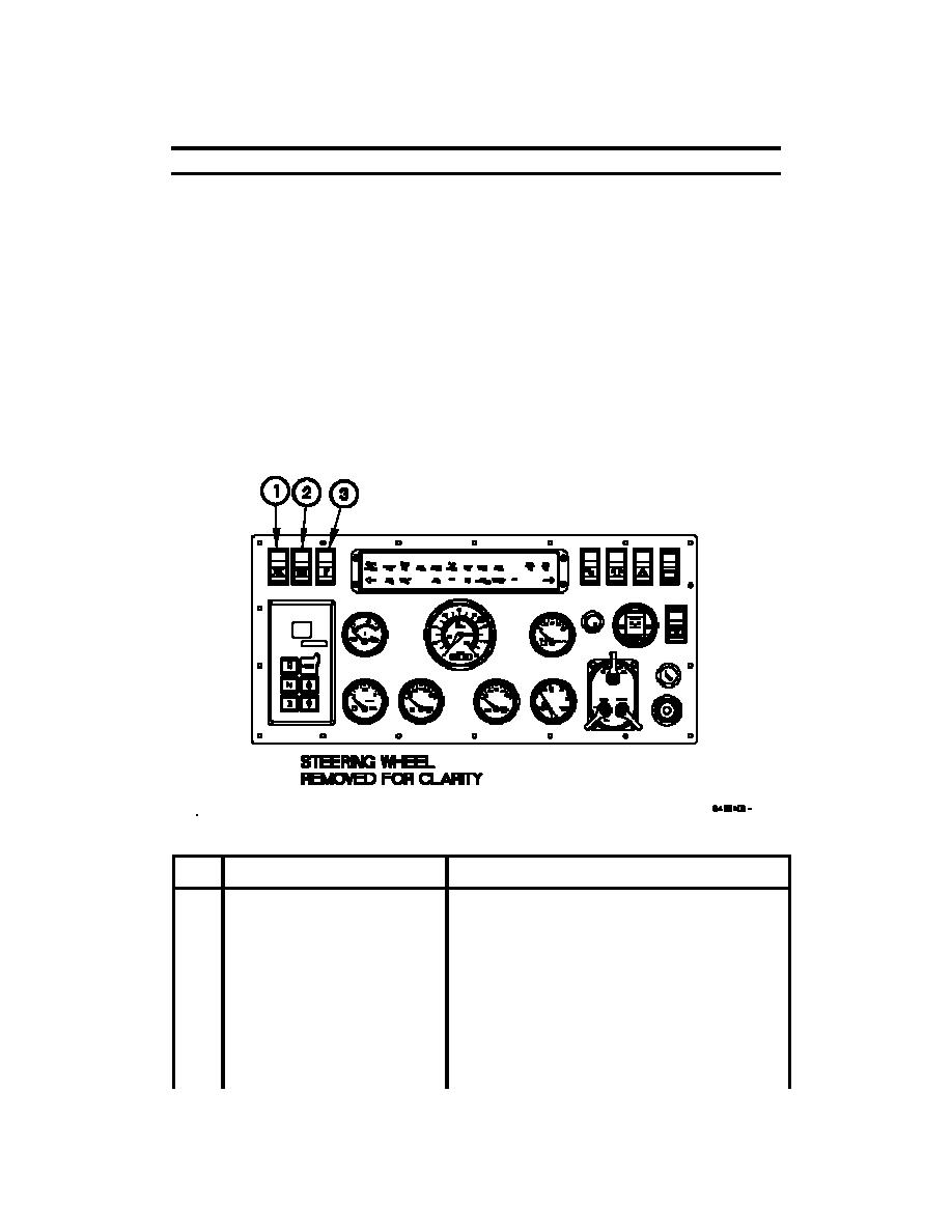
INSTRUMENT PANEL CONTROLS AND INDICATORS
0004 00
GENERAL
The following paragraphs contain illustrations that show the location of each control and
indicator for the M1078A1 series vehicles. Each control and indicator is clearly labeled as
it appears on the vehicle. Callouts on the illustration are keyed to the tabular listing which
contains the name, based on the panel markings, and the functional description of each
control and indicator.
INSTRUMENT PANEL ASSEMBLY CONTROLS AND INDICATORS
Table 1 describes controls and indicators on the instrument panel assembly (vehicle S/N
11,438 to 18,549).
Table 2 describes controls and indicators on the instrument panel assembly (vehicle S/N
18,550 to 99,999).
Table 3 describes controls and indicators on the instrument panel assembly (vehicle S/N
100,001 to 199,999).
Table 1. Instrument Panel Assembly Controls and Indicators (Vehicle S/N
11,438 to 18,549).
KEY
CONTROL OR INDICATOR
FUNCTION
1
Engine fan off switch
When positioned to on, the engine fan off switch
will disable engine fan and cause the ENGINE
FAN OFF indicator to illuminate. The Engine fan
off switch is only used to turn off the engine fan
during fording operations.
2
LAMP TEST switch
Tests all lights on Lighted Indicator Display.
3
Ether start switch
Injects ether into engine intake system to assist
with cold weather starting when switch is
pressed.
0004 00-1
|
|
Privacy Statement - Press Release - Copyright Information. - Contact Us |
