 |
|||
|
|
|||
|
Page Title:
TRANSMISSION CONTROL VALVE REPLACEMENT - continued |
|
||
| ||||||||||
|
|
 TM 9-2320-386-24-1-2
0371 00
TRANSMISSION CONTROL VALVE REPLACEMENT (Contd)
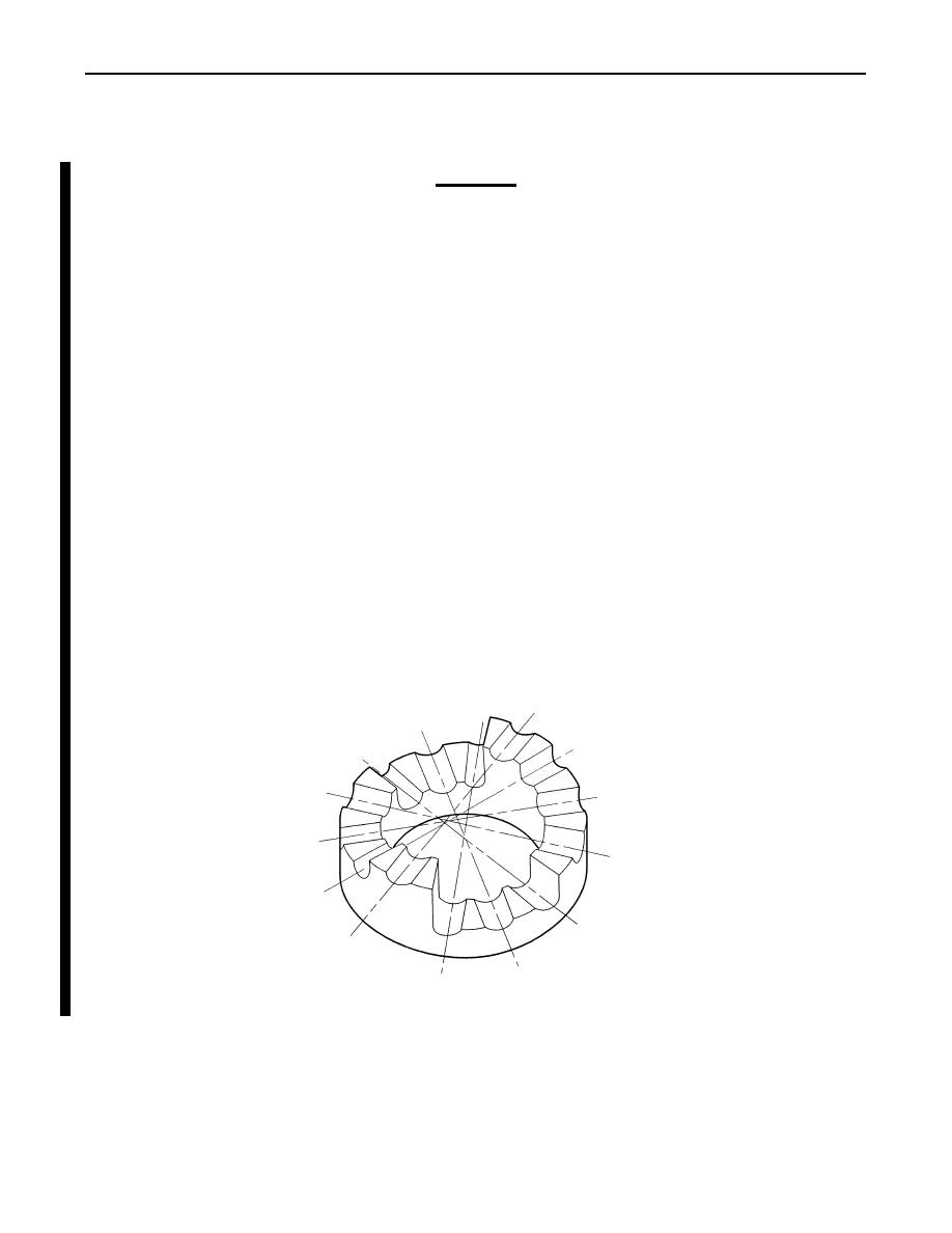
CAUTION
Adjusting rings are spring loaded. To retain original calibration of
valve assembly, adjusting rings must be installed in same
positions as when removed. Before removing retainer pins, record
positions of adjusting rings as shown below.
13.
Compress adjusting ring (7) and remove retainer pin (19) from control valve body (40). Remove
adjusting ring (7), washer (8), valve stop (9), valve spring (10), and hold regulator valve (11) from
bore (1) in control valve body (40).
NOTE
Configuration of 1-2 modulator valve bore differs for models with
second gear start. Note order parts are removed from bore.
14.
Compress adjusting ring (12) and remove retainer pin (18). Remove adjusting ring (12), stop (13),
spring (14), 1-2 modulator valve (15), 1-2 shift signal valve (16), and spring (17) from bore (2) in
control valve body (40).
15.
Compress adjusting ring (20) and remove retainer pin (25). Remove adjusting ring (20), stop (21),
spring (22), 2-3 modulator valve (23), and 2-3 shift signal valve (24) from bore (3) in control valve
body (40).
16.
Compress adjusting ring (26) and remove retainer pin (31). Remove adjusting ring (26), stop (27),
spring (28), 3-4 modulator valve (29), and 3-4 shift signal valve (30) from bore (4) in control valve
body (40).
17.
Hold stop (32) and remove retainer pin (35). Remove stop (32), spring (33), and 3-4 relay
valve (34) from bore (5) in control valve body (40).
18.
Hold stop (36) and remove retainer pin (39). Remove stop (36), spring (37), and trimmer regulator
valve (38) from bore (6) in control valve body (40).
G
A
B
F
C
D
E
E
D
F
C
G
B
A
ADJUSTING RING POSITIONS
Change 1
0371 00-6
|
|
Privacy Statement - Press Release - Copyright Information. - Contact Us |
