 |
|||
|
|
|||
|
Page Title:
FUEL SETTING ADJUSTMENT - continued |
|
||
| ||||||||||
|
|
 TM 9-2320-386-24-1-2
0323 00
FUEL SETTING ADJUSTMENT (Contd)
NOTE
If the control linkage positioning tool is left in position, it will
interfere with rack movement and prevent an accurate check or
adjustment of the fuel setting.
16. Loosen clamping screw on control linkage positioning tool.
17. Remove control linkage positioning tool from control linkage shaft (5).
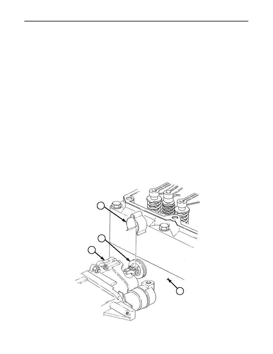
18. Remove clip (2) from governor sleeve (1).
19. Using soft-jawed pliers, rotate sleeve (1) back and forth to break loose the O-ring seal on sleeve (1).
NOTE
Ensure no nicks or scratches occur to sleeve while sliding sleeve
into intake manifold. Damage to sleeve may result in governor not
sealing properly.
20. Using soft-jawed pliers, slide sleeve (1) from governor (4) into cylinder head (3).
21. Install fuel setting pin in pin (6).
NOTE
Do not force the fuel setting wedge in too far. The wedge needs to
be in tight enough to hold the pin securely against the governor
housing, but too much pressure may cause the pin to flex and
distort the fuel setting reading.
22. Install fuel setting wedge between sleeve (1) and fuel setting pin. Ensure fuel setting wedge is
positioned to hold fuel setting pin securely against governor (4).
2
1
4
3
0323 00-6
|
|
Privacy Statement - Press Release - Copyright Information. - Contact Us |
