 |
|||
|
|
|||
|
Page Title:
POWER PLANT REPLACEMENT - continued |
|
||
| ||||||||||
|
|
 TM 9-2320-386-24-1-2
0295 00
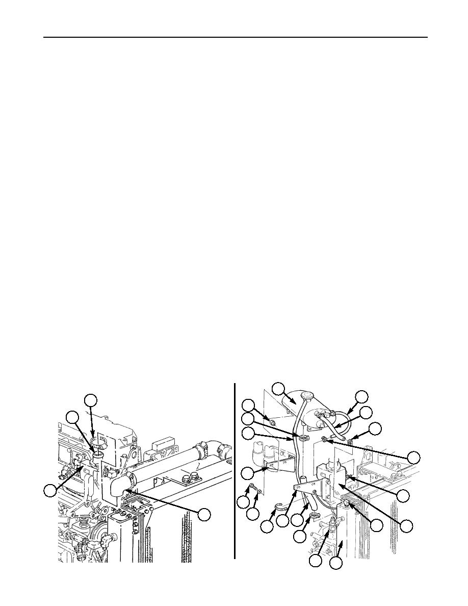
POWER PLANT REPLACEMENT (Contd)
8.
Remove clamp (2) and hose elbow (3) from flange (1) on thermostat housing (4).
9.
Remove clamp (8) and hose (7) from elbow (11) on radiator (12).
10.
Remove clamp (9) and hose (6) from fitting (10) on thermostat housing (4).
11.
Remove tiedown strap (17), vent line (21), clamps (14) and (22), and hose (15) from bottom of surge
tank (5) and fitting (13). Discard tiedown strap (17).
12.
Remove four locknuts (23), screws (19), washers (18), and surge tank (5) from brackets (16)
and (20). Discard locknuts (23).
NOTE
Vehicles may come equipped with a Leece-Neville or Prestolite
alternator. STE/ICE-R wiring harness leads are connected to negative
and positive posts on either alternator.
13.
Remove screw (27), lockwasher (26), ground (GND) terminal lead (25), and STE/ICE-R terminal
lead 770-P (36) from alternator (35). Discard lockwasher (26).
NOTE
Perform steps 14 and 15 for Prestolite alternators only.
Perform step 16 for Leece-Neville alternators only.
14.
Remove two screws (24), lockwashers (40), and plate (39) from alternator (35). Discard
lockwashers (40).
15.
Remove two assembled-washer screws (28) and cover plate (29) from alternator (35). Discard
assembled-washer screws (28).
16.
Remove two screws (28), lockwashers (41), and cover plate (29) from alternator (35). Discard
lockwashers (41).
17.
Remove nut (30), lockwasher (31), positive terminal lead 2 (32), and STE/ICE-R terminal lead
770-N (33) from positive post (34). Discard lockwasher (31).
18.
Disconnect lead 568 (37) from Y-connector (38).
19.
Disconnect plug with wires 569-B and ground (GND) leads (56) from temperature switch connector (57).
20.
Disconnect plug lead 33 (45) from temperature sending unit connector (44).
21.
Remove screw (55), clamp (54) with harness (53), ground (GND) lead (52), and lockwasher (51) from
bracket (50). Discard lockwasher (51).
22.
Remove actuator air lines (42) and (49) from fittings (43) and (58), and air line (49) and grommet (48)
from bracket (16).
23.
Remove fan actuator air line (47) from fan actuator (46).
5
6
2
~
23
7
1
22
8
21
9
~
20
~
4
10
19
18
3
16 15
11
4
17
~
14
13
12
0295 00-4
|
|
Privacy Statement - Press Release - Copyright Information. - Contact Us |
