 |
|||
|
|
|||
|
Page Title:
SPEED CONTROL CABLE MAINTENANCE - continued |
|
||
| ||||||||||
|
|
 TM 9-2320-361-24-2
0294 00
SPEED CONTROL CABLE MAINTENANCE (Contd)
WARNING
Diesel fuel is flammable. Do not perform fuel system procedures
near open flames. Injury or death to personnel may result.
REMOVAL
1.
Remove cotter pin (16) and pin (17) from eye (18) and fuel pump lever (2). Discard cotter pin (16).
2.
Loosen two nuts (14) and remove cable assembly (15) from bracket (3).
3.
Remove cotter pin (9) and pin (12) from eye (10) and rod assembly (7). Discard cotter pin (9).
4.
Remove two screws (5), lockwashers (6), and bracket (8) from cab frame (4). Discard
lockwashers (6).
5.
Loosen two nuts (13) and remove cable (15) from bracket (8).
6.
Loosen two nuts (11) and remove two eyes (10) and (18) from cable (15).
INSPECTION
Inspect bracket (8) for cracks and bends. Replace bracket (8) if cracked or bent.
INSTALLATION
1.
Install two eyes (10) and (18) on cable assembly (15) and tighten two nuts (11).
NOTE
Access to bracket is through door in cab floor in front of driver's
seat.
2.
Install bracket (8) on frame (4) with two screws (5) and new lockwashers (6).
3.
Install cable (15) on fuel pump lever (2) with pin (17) and new cotter pin (16).
4.
Install cable (15) on rod assembly (7) with pin (12) and new cotter pin (9).
NOTE
Loosen nuts to adjust cable so fuel pump lever is in curb idle
position.
5.
Install cable (15) on two brackets (3) and (8) and tighten two nuts (14) and (13).
ADJUSTMENT
1.
Start engine and engage PTO (TM 9-2320-361-10). Monitor rpm with STE/ICE-R.
2.
Adjust screw (1) and wire (19) to obtain fuel pump lever (2) position for RPMs specified for each
vehicle. Refer to table 1 for settings.
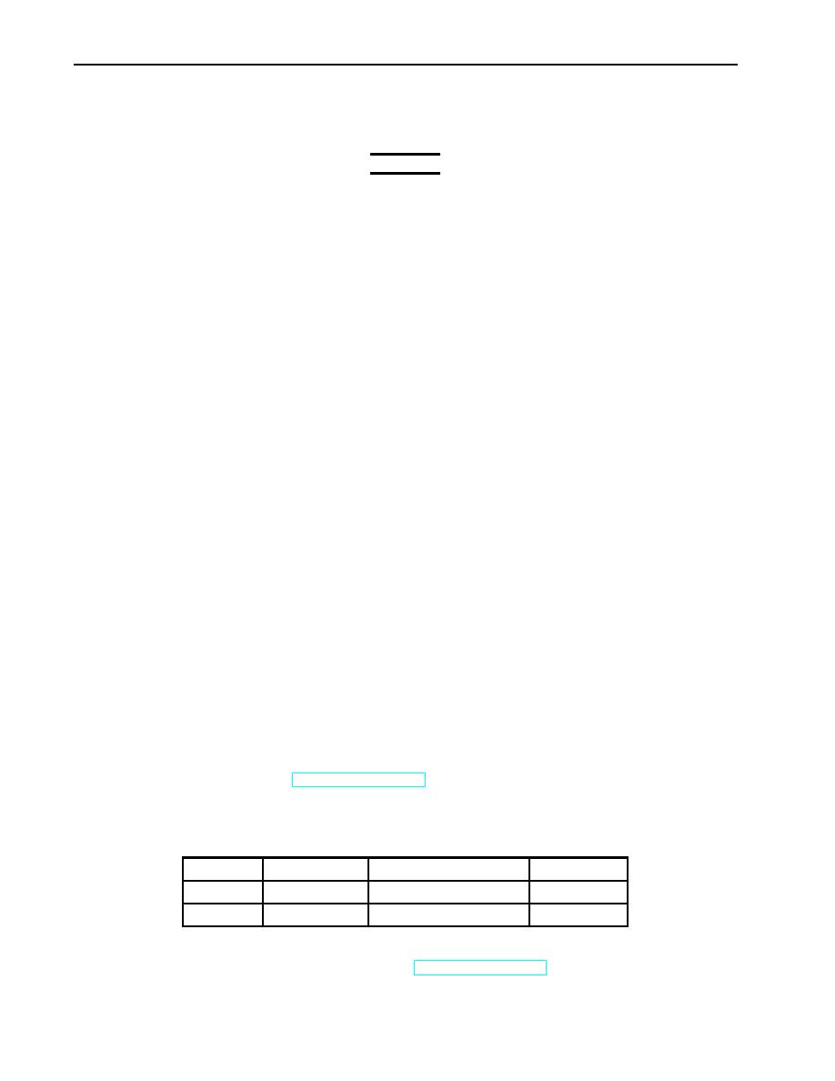
Table 1. Speed Control Adjustment.
MODEL
ENGINE RPM
TRANSMISSION GEAR
PTO RPM
M49A2C
1150
2nd
413
M50A3
1100
4th
1100
3.
Connect battery ground cable (WP 0126 00).
4.
Release parking brake and remove wheel chocks (TM 9-2320-361-10).
0294 00-2
|
|
Privacy Statement - Press Release - Copyright Information. - Contact Us |
