 |
|||
|
|
|||
|
Page Title:
WATER TANK DISCHARGE VALVE CONTROL LEVERS MAINTENANCE (M50A3) - continued |
|
||
| ||||||||||
|
|
 TM 9-2320-361-24-2
0290 00
WATER TANK DISCHARGE VALVE CONTROL LEVERS MAINTENANCE (M50A3) (Contd)
CONTROL LEVERS DISASSEMBLY
CAUTION
Do not strike levers or brackets during lever shaft removal.
Striking levers or brackets may result in damage to
components.
1.
Remove three screws (14) and lockwashers (15) from brackets (16), (20), and (24). Discard
lockwashers (15).
NOTE
Prior to removal, tag all component locations for assembly.
2.
Remove lever shaft (21) from bracket (24), lever (25), bracket (20), lever (5), and bracket (16).
Remove levers (5) and (25).
3.
Remove three screws (1), lockwashers (2), and spacer bar (3) from brackets (16), (20), and (24).
Discard lockwashers (2).
4.
Remove spacers (18) and (22) from bushings (17), (19), and (23).
LEVER DISASSEMBLY
1.
Remove cotter pin (7), straight pin (4) and control handle (6) from lever (5).
2.
Remove straight pin (8), connecting links (9) and (12), from lever (5).
3.
Remove shoulder screw (13), spring (10), and lock release lever (11) from lever (5).
CLEANING AND INSPECTION
1.
Refer to WP 0021 00 for general cleaning and inspection instructions.
2.
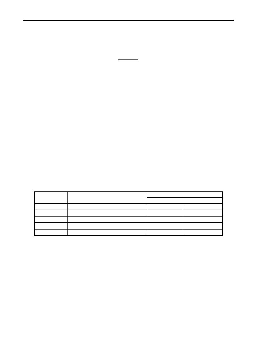
Refer to table 1 for lever assembly area limits.
Table 1. M50A3 Water Tank Discharge Valve Control Levers Wear Limits.
WEAR LIMITS/TOLERANCES
ITEM NO.
ITEM/POINT OF MEASUREMENT
INCHES
MILLIMETERS
21
Lever shaft (diameter)
0.8600.885
in.
21.8422.48
mm
5 and 25
Levers (inner diameter at shaft hole)
0.8680.992
in.
22.0523.42
mm
17, 19, and 23
Bushings (outer diameter)
0.4360.438
in.
11.0711.13
mm
18 and 22
Spacers (inner diameter)
0.4400.444
in.
11.1811.28
mm
18 and 22
Spacers (outer diameter)
0.7200.780
in.
18.2919.81
mm
3.
Inspect spacers (18) and (22) for flat spots or wear. Refer to table 1 for measurements. Replace
spacers (18) and (22) if not within wear limits.
4.
Inspect bushings (17), (19), and (23) for grooves or wear. Refer to table 1 for measurements.
Replace bushings (17), (19), and (23) if not within wear limits.
5.
Inspect brackets (16), (20), and (24) for cracks or damage. Replace brackets (16), (20), and (24) if
cracked or damaged.
NOTE
Perform steps 6 through 8 if bushings or brackets are damaged
or not within wear limits.
6.
Press bushings (17), (19), and (23) from brackets (16), (20), and (24). Discard bushings (17), (19),
and (23).
7.
Install new bushings (17) and (23) in brackets (16) and (24) with press until bushings (17) and (23)
ends are flush with brackets (16) and (24).
0290 00-2
|
|
Privacy Statement - Press Release - Copyright Information. - Contact Us |
