 |
|||
|
|
|||
|
Page Title:
DISCHARGE VALVE CONTROL LEVERS MAINTENANCE (M49A2C) - continued |
|
||
| ||||||||||
|
|
 TM 9-2320-361-24-2
0264 00
DISCHARGE VALVE CONTROL LEVERS MAINTENANCE (M49A2C) (Contd)
DISASSEMBLY
CAUTION
Do not strike levers or brackets during lever shaft removal.
Striking levers or brackets may result in damage to
components.
NOTE
Prior to removal, tag all components for assembly.
1.
Remove springs (31) and (22) from lever arms (14) and (21) and brackets (30) and (23).
2.
Remove three screws (6) and lockwashers (7) from brackets (5), (30), and (23). Discard
lockwashers (7).
3.
Remove lever shaft (8) and levers (4) and (28) from between brackets (5), (30), and (23).
4.
Remove cotter pins (15) and (16) and fusible link (17) from lever arm (14) and bracket (30).
Discard cotter pins (15) and (16).
5.
Remove setscrews (12) and (20) in cams (13) and (19). Remove shaft (9) from bushing (24), lever
arm (21), cam (20), bushing (29), lever arm (14), cam (13), and bushing (10). Remove cams (13)
and (20).
6.
Remove rollers (18) and (11) from bushings (10) and (29).
7.
Remove lever arms (14) and (21) from bushings (29) and (24).
8.
Remove cotter pin (27) from pin (25) and remove pin (25) and clevis (26) from lever arm (21).
Discard cotter pin (27).
9.
Remove three screws (2), lockwashers (3), and spacer bar (1) from brackets (5), (30), and (23).
Discard lockwashers (3).
CLEANING AND INSPECTION
1.
Refer to WP 0021 00 for general cleaning instructions.
2.
Refer to WP 0020 00 for general inspection instructions.
3.
Inspect clevis (26) and pin (25) for cracks or pin hole damage. Replace clevis (26) and pin (25) if
cracked or pin hole is damaged.
4.
Inspect shaft (9) for twists, cracks, or breakage. Replace shaft, (9) if twisted, cracked, or broken.
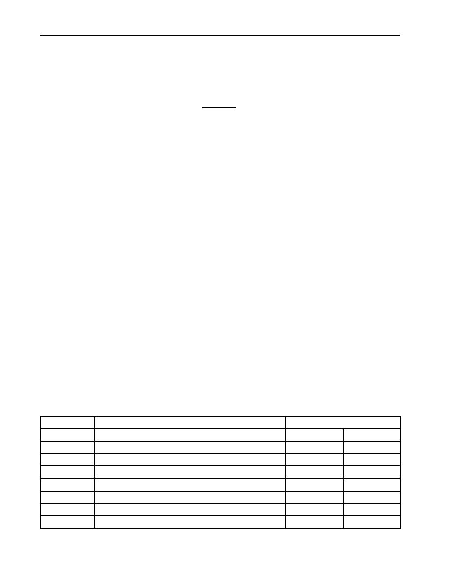
ITEM NO
ITEM/POINT OF MEASUREMENT
WEAR LIMITS/TOLERANCE
INCHES
MILLIMETERS
21
Lever arm (inner diameter at shaft hole)
0.4.330.463
11.2511.76
14
Lever arm (inner diameter at shaft hole)
0.4300.454
10.9211.53
4 and 28
Levers (inner diameter at shaft hole)
0.8680.922
22.0523.42
10, 24, and 29 Bushings end exposed (diameter)
0.4300.438
10.9211.13
8
Lever shaft (diameter)
0.8600.885
21.8422.48
11 and 18
Roller (outer diameter)
0.750
19.05
11 and 18
Roller (inner diameter)
0.4400.444
11.1811.28
0264 00-2
|
|
Privacy Statement - Press Release - Copyright Information. - Contact Us |
