 |
|||
|
|
|||
|
Page Title:
ROCKER ARMS AND PUSHRODS MAINTENANCE - continued |
|
||
| ||||||||||
|
|
 TM 9-2320-361-24-1
0031 00
ROCKER ARMS AND PUSHRODS MAINTENANCE (Contd)
ADJUSTMENT
WARNING
Disconnect battery ground cable prior to performing valve
adjustment procedure. Failure to do so may cause injury to
personnel.
1.
Disconnect battery ground cable (WP 0126 00).
NOTE
The intake valve is the front valve and the exhaust valve is
the rear valve in each cylinder.
Cylinders are numbered from the front of the truck to the
rear.
Assistant will help with this procedure.
2.
Rotate crankshaft bolt (1) clockwise until rocker arm (2), No. 1 cylinder intake valve, is fully open.
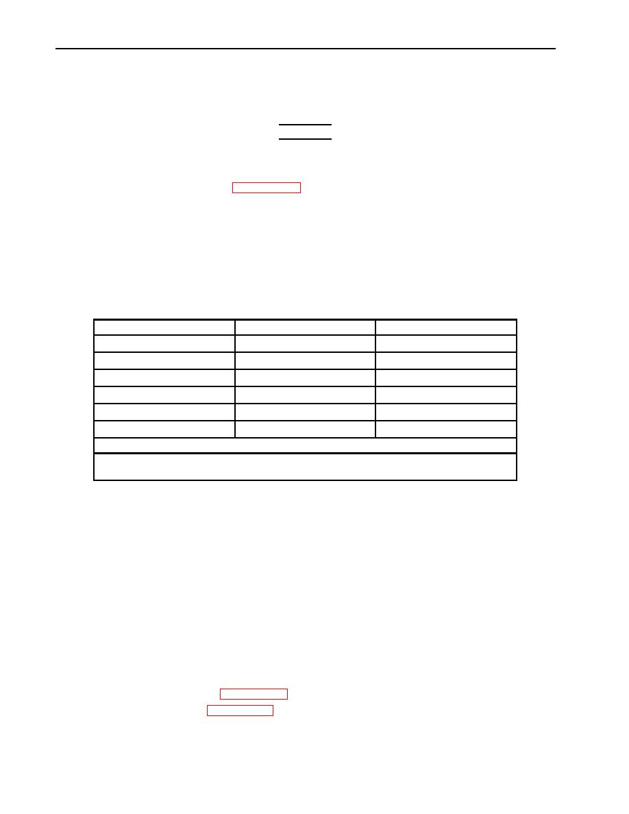
Table 2. Valve Clearance Limits.
CYLINDER NUMBER
VALVES ADJUSTED IN STEP 4
VALVES ADJUSTED IN STEP 11
1
E
I
2
I and E
3
I
E
4
E
I
5
I and E
6
I
E
VALVE CLEARANCE SETTING
I=Intake valve gap 0.010 in. (0.254 mm)
E= Exhaust valve gap 0.025 in. (0.635 mm)
3.
Adjust valves to proper clearance. Refer to table 2, Valve Clearance Limits, for measurements.
Perform steps 5 through 8.
NOTE
All rocker levers are adjusted the same way.
4.
Loosen nut (6) and turn adjustment screw (5) two full turns counterclockwise.
5.
Place feeler gauge between rocker arm head (4) and valve stem (7).
6.
Tighten or loosen adjustment screw (5) until a slight drag is felt on feeler gauge.
7.
Hold adjustment screw (5) stationary and tighten nut (6).
8.
When all valves in step 4 are adjusted, perform steps 10 and 11.
9.
Rotate crankshaft bolt (1) 360 clockwise until rocker arm (3), No. 6 cylinder intake valve,
is fully open.
10.
Adjust remaining valves to proper clearance. Refer to table 2, Valve Clearance Limits, for
measurements. Repeat steps 5 through 8 to adjust remaining valves.
11.
Connect battery ground cable (WP 0126 00).
12.
Install rocker arm cover(s) (WP 0030 00).
0031 00-8
|
|
Privacy Statement - Press Release - Copyright Information. - Contact Us |
