 |
|||
|
|
|||
|
Page Title:
Inspection and Repair - continued |
|
||
| ||||||||||
|
|
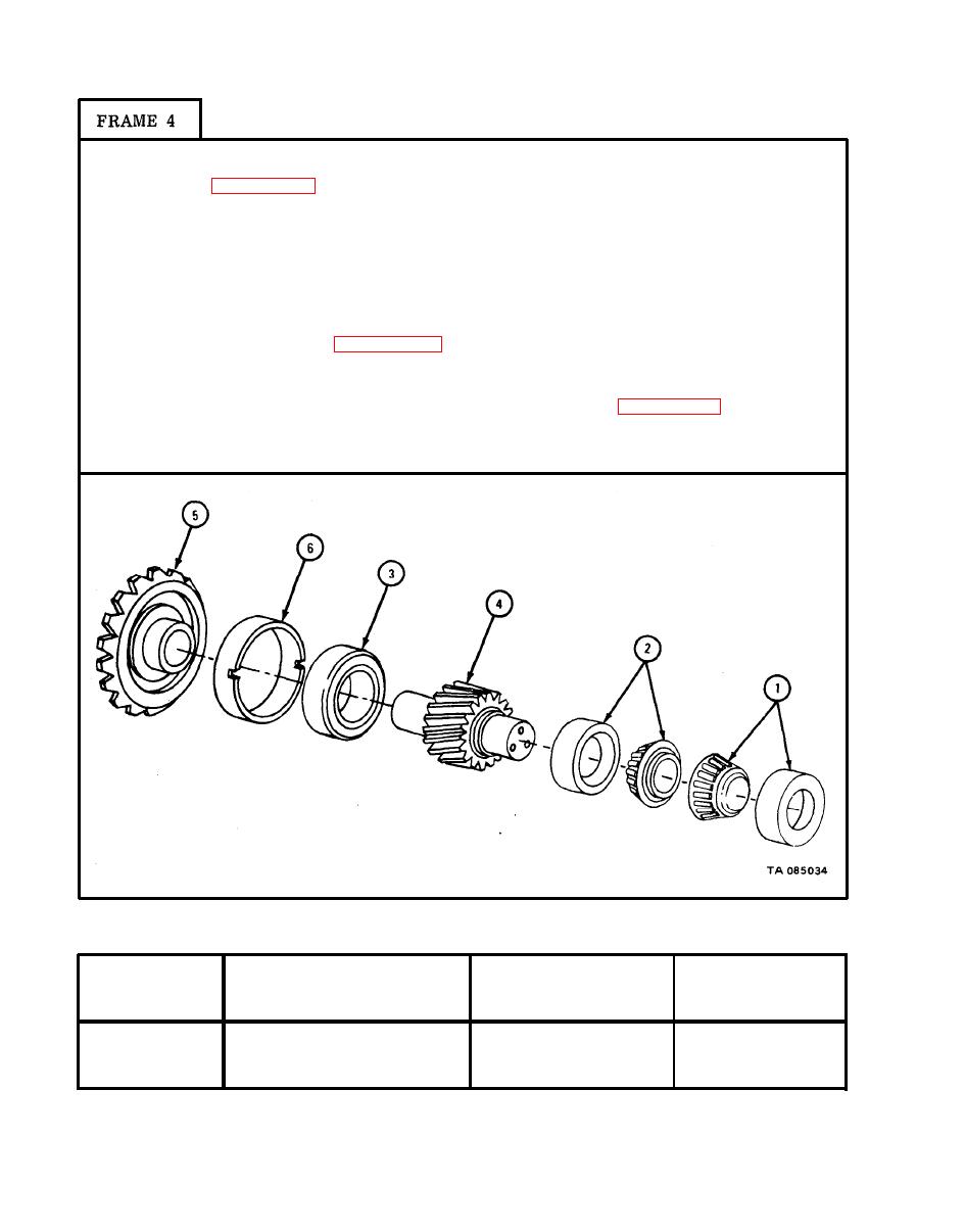 TM 9-2320-209-34-2-1
Check that bearing assemblies (1 and 2) and bearing (3) are not damaged.
1.
Refer to para 10-8.
2.
Using inside micrometer, measure inner diameter of cones of bearing assemblies
(1 and 2). Note measurements.
3.
Using outside micrometer, measure outer diameter of outer shaft end of spur
gear pinion (4). Note measurement.
4.
Subtract measurement made in step 3 from measurement made in step 2. Check
that fits of bearing assembly cones (1 and 2) to spur gear pinion (4) are
within limits given in table 10-7. If fits of cones of bearing assembly are not
within limits given, get new parts for worn one.
Do steps 2 through 4 again and check that fits of bearing (3) to hypoid
5.
drive gear (5) and sleeve (6) are within limits given in table 10-7. Get new
parts for parts worn beyond limits.
GO
TO FRAME 5
L shows a loose fit.)
Size and Fit
of New Parts
Wear Limit
Number
Item/Point of Measurement
(inches)
(inches)
Fit of bearing on shaft
1 amd 2 to 4
0.0000T to 0.0015T
None
3 to 5
Fit of bearing in sleeve
0.0032L to 0.0056L
None
|
|
Privacy Statement - Press Release - Copyright Information. - Contact Us |
