 |
|||
|
|
|||
|
Page Title:
ACCELERATOR CONTROLS AND LINKAGES REMOVAL, REPAIR, REPLACEMENT, AND ADJUSTMENT - continued |
|
||
| ||||||||||
|
|
 TM 9-2320-209-20-3-1
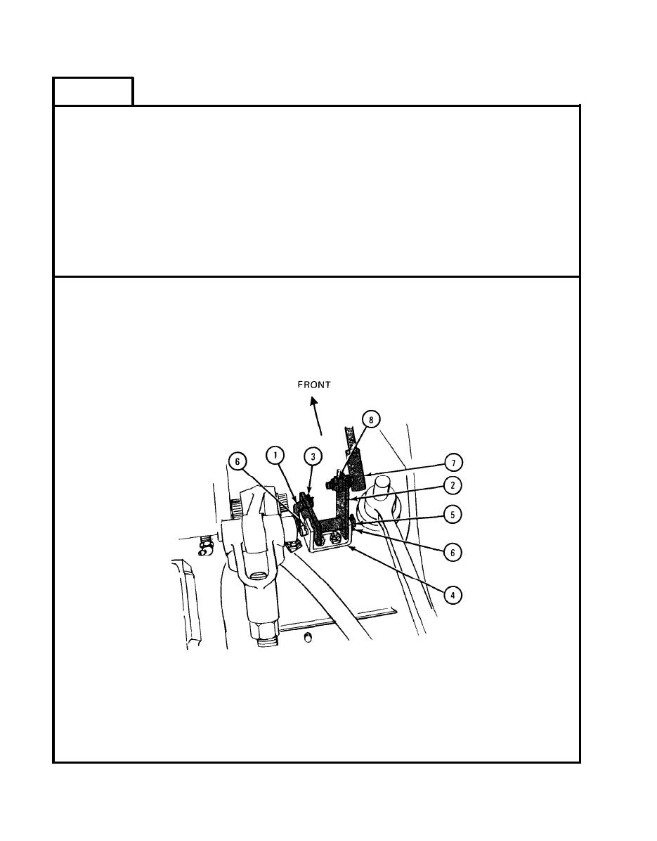
FRAME 2
1.
Put end of connecting link (1) through hole in lever assembly (2) as shown. Put
cotter pin (3) through hole in end of connecting link. Using pliers, spread cotter
pin.
Put headless pin (5) through holes
2.
Place lever assembly (2) in bracket (4) as shown.
in bracket and lever assembly.
3.
Put two cotter pins (6) through holes in headless pin (5). Using pliers spread cotter
pins .
4.
Put stud of ball joint (7) through hole in lever assembly (2) as shown. Using
1/2-inch wrenches, screw on and tighten locknut (8).
GO TO FRAME 3
TA 047148
4-170
|
|
Privacy Statement - Press Release - Copyright Information. - Contact Us |
